background image

IM25OM-1/2000-250

14

___________________________________________________________________________________________________________________________________________

___________________________________________________________________________________________________________________________________________

___________________________________________________________________________________________________________________________________________

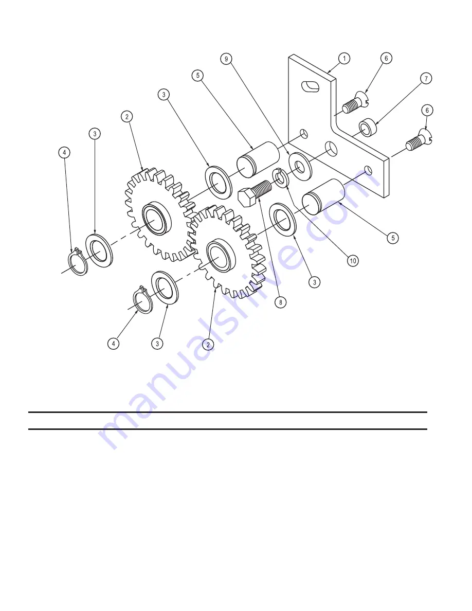
FIGURE 6—BACKLAP GEAR ASSEMBLY, 400104

Item

Description

Part No.

Qty.

1

400106

BRACKET

1

2

400105

GEAR, with Bushing, 24 Tooth

2

3

02502

WASHER

4

4

04020

LOCKRING, 3/4”

2

5

400109

PIN, Gear

2

6

02148

SCREW, Flat Head Slotted, 5/16”–18 X 3/4”

2

7

200676

BUSHING

1

8

02034

CAPSCREW, 3/8”–16 X 3/4”

1

9

02403

WASHER, Flat, 3/8”

1

10

02303

LOCKWASHER, 3/8”

1

Содержание IM25

Страница 1: ...NATIONAL MOWER CO 700 Raymond Ave P O Box 14299 St Paul Minnesota 55114 0299 U S A Phone 651 646 4079 Fax 651 646 2887 www nationalmower com JANUARY 2000 IM25 INFIELD MOWER OWNER S MANUAL ...

Страница 2: ...st be noted by the consignee at the point of designation and filed with the transportationcompany 1 Carefully uncrate the machine 2 Attach the lower Handle Bar Assembly 1 Fig B to the Handle Bar Brackets 2 Fig A with pivot pins flat washers and cotter pins from the loose partsbag 3 Insert Handle Adjustment Rods 3 Fig A into Lower Handle Bar Assembly and Adjustment Brackets 4 Fig A on countershaft ...

Страница 3: ...n the lower position if the cutting height is over 1 and the upper position if the cutting height is 1 or less Disassembly of the rear roller assembly is necessary to change the bearing location See Figure 4 for reference Reel blades are sharp Never attempt to adjust cutting height of reel to bed knife while the engine is running 2 Adjust cutting height by loosening the top and bottom Adjusting Nu...

Страница 4: ...NATIONAL IM25 Infield Mower 5 FIGURE A FIGURE B FIGURE C ...

Страница 5: ...lap assembly pivot assembly rearward and tighten hex nut as shown in Figure D 5 Start engine and run at half throttle Engage drive clutch 6 With reel running apply lapping compound to the reel with a 2 or 3 brush Apply compound evenly to themovingblades Be extremely careful not to let the brush your fingers or your clothing get caught in the reel Use approved safety glasses and gloves to protect y...

Страница 6: ...ress and phone number 2 Model Number and Serial Number located on the rear side of the top plate 3 PartNumber itisrecommendedthatthecorrectnumberbeverified with a current Master Price List 4 The full Description of the part 5 Quantity desired quantity shown is the total number of parts con tained in the particular view shown If the Part Number and the Description of your order do not agree the Par...

Страница 7: ...IM25OM 1 2000 250 8 FIGURE 1 ...

Страница 8: ...________________________________________________________________________________ ___________________________________________________________________________________________________________________________________________ ___________________________________________________________________________________________________________________________________________ _______________________________________...

Страница 9: ..._______________________________________________________________________________________________ FIGURE 2 GROUND DRIVE COUNTERSHAFT ASSEMBLY 400040 Item Description Part No Qty 1 03117 SPROCKET 14Tooth 1 2 03634 PULLEY 1 3 06136 BEARING 2 4 400020 PLATE Bearing Carrier Short 1 5 400063 PLATE BearingCarrier Long 1 6 400069 RETAINER ClutchCable 1 7 400095 COUNTERSHAFT RollerDrive 1 8 202436 Key 9 Woo...

Страница 10: ...__________________________________________________________________________________________________________ FIGURE 3 REEL DRIVE COUNTERSHAFT 400041 Item Description Part No Qty 1 202839 SPROCKET 24Tooth 1 2 03634 PULLEY 1 3 06136 BEARING 2 4 400020 PLATE Bearing Carrier Short 1 5 400063 PLATE BearingCarrier Long 1 6 400069 RETAINER ClutchCable 1 7 400096 COUNTERSHAFT ReelDrive 1 8 202436 KEY 9 Wood...

Страница 11: ..._______________________________________________________________________________________________________________ FIGURE 4 REAR ROLLER ASSEMBLY 400038 Item Description Part No Qty 1 400037 TUBE Roller 2 2 400097 SHAFT Roller 1 3 400013 RING Pinion 2 4 400014 RETAINER Pinion 2 5 04531 SPRING Pinion Pawl 2 6 09077 PAWL Pinion 2 7 202436 KEY 9 Woodruff 2 8 06140 BEARING 4 9 02502 WASHER 1 ...

Страница 12: ...________________________________________________________________________________________ FIGURE 5 CLUTCH ASSEMBLY 400100 Item Description Part No Qty 1 400044 BRACKET MowingClutch 1 2 400099 BRACKET Clutch Mount 1 3 400080 BRACKET TransportClutch 1 4 03608 PULLEY 2 5 200676 BUSHING 2 ...

Страница 13: ...______________ ___________________________________________________________________________________________________________________________________________ FIGURE 6 BACKLAP GEAR ASSEMBLY 400104 Item Description Part No Qty 1 400106 BRACKET 1 2 400105 GEAR with Bushing 24 Tooth 2 3 02502 WASHER 4 4 04020 LOCKRING 3 4 2 5 400109 PIN Gear 2 6 02148 SCREW Flat Head Slotted 5 16 18 X 3 4 2 7 200676 BUSH...

Страница 14: ...engines enginepartsortireswhicharecovered under separate warranties furnished by their manufacture or supplier All service under this warranty will be furnished and performed by our Factory Authorized Service Stations THERE IS NO OTHER EXPRESS WARRANTY IMPLIEDWARRANTIES INCLUDINGTHOSEOFMERCHANTABILITYAND FITNESS FOR A PARTICULAR PURPOSE ARE LIMITED TO ONE YEAR FROM PURCHASE OR 45 DAYS IF THE PRODU...

Отзывы: