


UMI Accessory User Guide — UMI-4A
14
www.natinst.com
The analog output signals are used as command outputs to a servo
amplifier. The System Inhibit output signals are used to disable all of the
amplifiers. The UMI accessory combines the host bus interlock circuit and
the Enable Input signals to create the global System Inhibit signals. The
host bus interlock monitors the +5 V pin from the motion controller to
verify that the controller is powered and properly connected to the UMI. If
the host bus interlock detects a problem, or if both Enable Input signals are
deasserted, the System Inhibit signals are asserted.
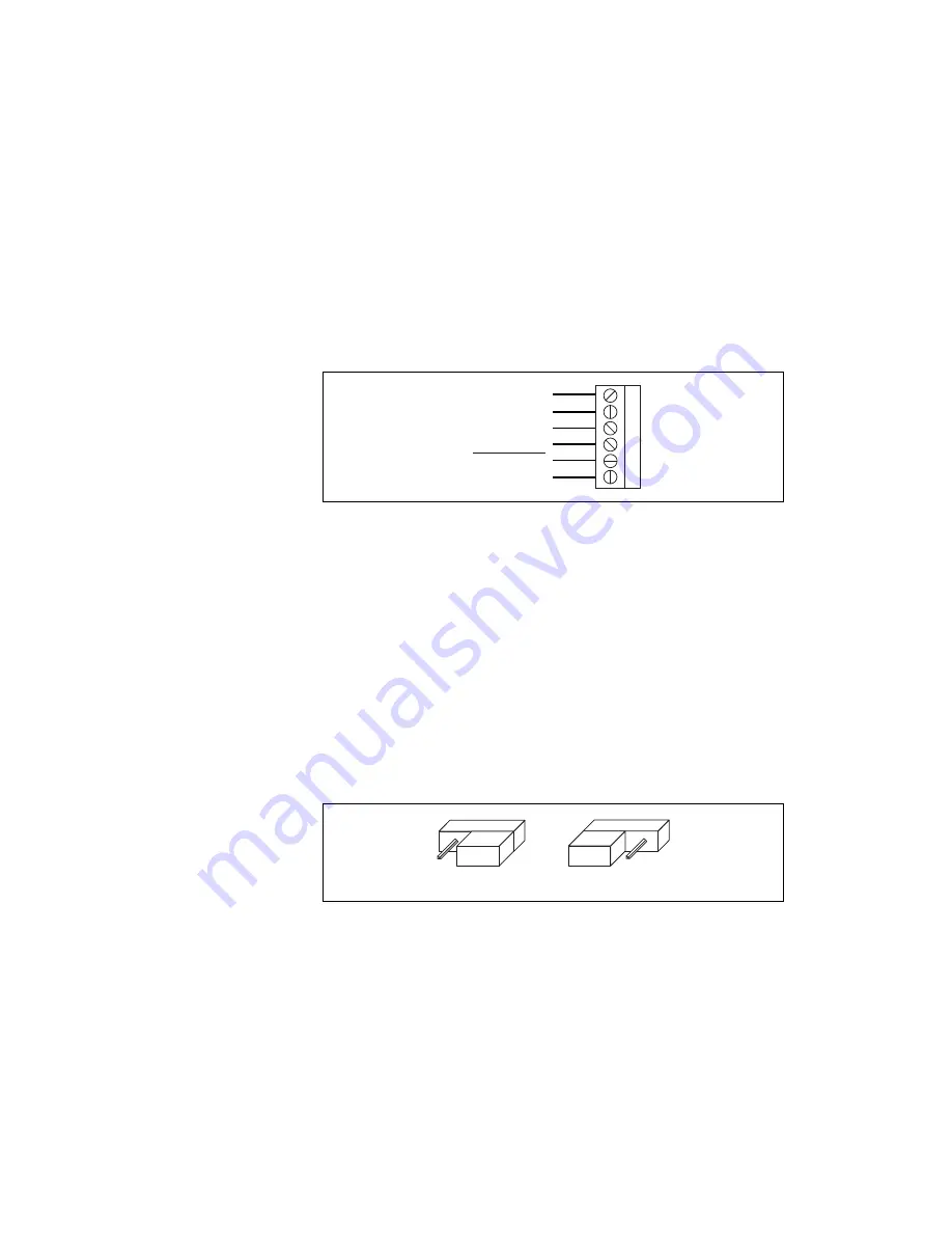
Figure 14 shows the UMI-4A amplifier/driver terminal block pin
assignment used with a stepper board.
Figure 14.
UMI-4A Amplifier/Driver with Stepper Terminal Block Pin Assignment
The Step and Dir signals are used as command outputs to a stepper driver.
The Inhibit Output signals are used to disable the driver for that axis. The
UMI accessory combines the host bus interlock circuit, the Enable Input
signals, and the per axis controller Inhibit Output to create the per axis
Inhibit Output signal. If the voltage drops to the host bus interlock circuit,
if both Enable Inputs are deasserted, or if the controller Inhibit Output for
that axis is asserted, the Inhibit Output signal for that axis is asserted.
To configure your UMI-4A accessory for servo, move all four jumpers to
the right. To configure your accessory for stepper, move all four jumpers to
the left. See Figure 15 for more information on configuring your UMI-4A
jumpers. Refer to Figure 12 to help you locate the jumpers on your
UMI-4A accessory.
Figure 15.
UMI-4A Jumper Configuration
1
2
3
4
5
Step (CW)
Dir (CCW)
6
I/O Bit (Axis #)
+5 V (Output)
Digital Ground
Inhibit Output
Servo
Stepper
Содержание UMI-7764
Страница 35: ......