©
National Instruments Corporation
23
UMI Accessory User Guide — UMI-Flex6
Power for the encoders is internally routed from the power input terminal
block and is available on pin 7 (+5 V). You must supply a +5 V source to
the power input terminal block for proper operation. Refer to Figure 23 to
help you locate the encoder terminal blocks on your UMI-Flex6 accessory.
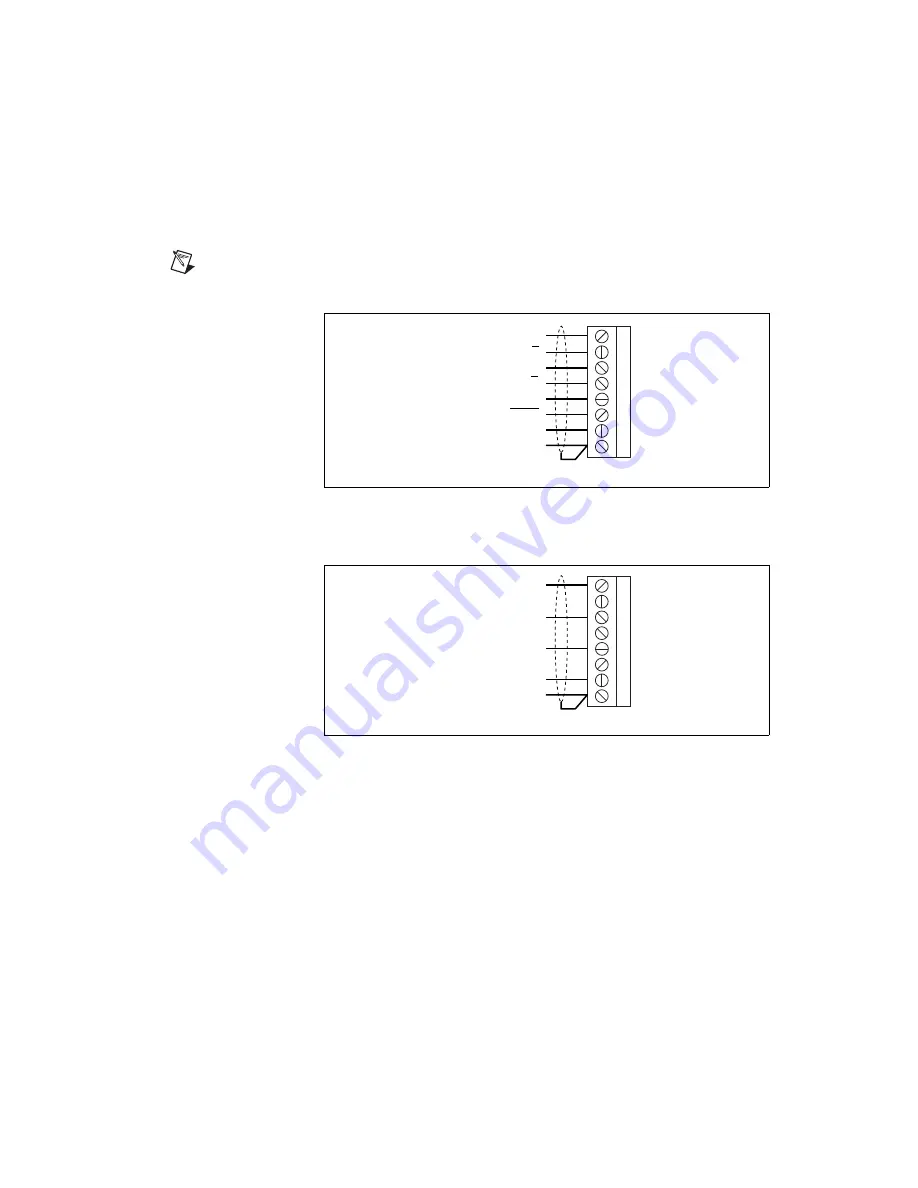
Figure 25 shows the wiring for the differential encoder.
Note
The dotted loop indicates a shielded cable.
Figure 25.
Differential Encoder Wiring
Figure 26 shows the wiring for the single-ended encoder.
Figure 26.
Single-Ended Encoder Wiring
The UMI-Flex6 accessory allows for differential inputs for Phase A,
Phase B, and Index signals. You can easily accommodate encoders with
phase relationships different from Figure 27 by swapping the signals as
required by the specific application. The Index pulse must occur when both
Phase A and Phase B signals are logic low as shown in Figure 27. Servo and
closed-loop stepper applications require encoder feedback and consistent
directional polarity between the motor and encoder for stable operation.
The UMI-Flex6 uses the following standards for motor direction:
•
Positive = forward = Clockwise (CW) facing motor shaft
•
Negative = reverse = Counter-clockwise (CCW) facing motor shaft
1
2
3
4
5
6
7
8
Phase A
Phase B
Phase B
Index
Index
+5 V (Output)
Digital Ground
Phase A
Shield
1
2
3
4
5
6
7
8
Phase A
Phase B
Index
+5 V (Output)
Digital Ground
Shield
Содержание UMI-4A
Страница 35: ......


