


Chapter 3
Theory of Operation
©
National Instruments Corporation
3-5
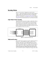
MOSI, MISO, SPICLK, and SS* form a synchronous communication link
that conforms with SPI using an idle-high clock and second-edge data
latching. D*/A, INTR*, and RESET* are additional control signals.
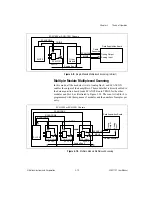
When the module is being used in an SCXI-1000 or SCXI-1001 chassis, the
data acquisition board, via the module rear signal connector, must tap into
the open-collector backplane signal lines as a master to write to the module.
The signal connections from the rear signal connector to the backplane are
shown in Table 3-1.
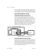
The SCXI-1121 module converts the data acquisition board signals to
open-collector signals on the backplane of the SCXI chassis. In order for
the data acquisition board to talk to a slot, the board must first assert the SS*
for that slot. This is done by asserting INTR* low, writing a 16-bit number
over MOSI corresponding to the desired slot (and chassis if an SCXI-1001
A24
TRIG0
TRIG0—General-purpose trigger line used by the
SCXI-1121 to send SCANCLK to other modules
or receive SCANCLK from other modules. Open
collector. I/O.
B24
SS*
Slot Select—When low, enables module
communications over the SCXIbus. Totem pole.
Input.
C24
SCANCON
Scanning Control—Combination output enable
and reload signal for scanning operations. Totem
pole. Input.
All other pins are not connected.
Table 3-1.
SCXIbus Equivalents for the Rear Signal Connector
Rear Signal
Connector Signal
SCXIbus Equivalent
SERDATIN
MOSI
DAQD*/A
D*/A
SLOT0SEL*
INTR* Jumper W44 must be set to position 1
SERCLK
SPICLK
SERDATOUT
MISO Jumper W38 must be set to position 1
Pin
Signal Name
Description


