manualshive.com logo in svg
background image

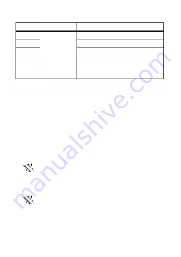
Table 9. Mini-HDMI Breakout Cable to 6 BNC Signal Descriptions

Signal

Connector Type

Description


CLK IN

BNC female

Used to import an external reference clock

CLK OUT

Used to export the reference clock

PFI 0

Bidirectional PFI line

PFI 1

Bidirectional PFI line

PFI 2

Bidirectional PFI line

PFI 3

Bidirectional PFI line

Configuring the PXIe-5164 in MAX

Use Measurement & Automation Explorer (MAX) to configure your NI hardware. MAX
informs other programs about which NI hardware products are in the system and how they are
configured. MAX is automatically installed with LabVIEW Instrument Design Libraries for
Reconfigurable Oscilloscopes.

MAX in also installed with NI-SCOPE.
1.

Launch MAX.

2.

In the configuration tree, expand 

Devices and Interfaces

 to see the list of installed NI

hardware.

Installed modules appear under the name of their associated chassis.

3.

Expand your 

Chassis

 tree item.

MAX lists all modules installed in the chassis. Your default names may vary.

Note


PXIe-5164 modules appear as NI-RIO devices in the list. If you do not

see your module listed, press <F5> to refresh the list of installed modules. If the
module is still not listed, power off the system, ensure the module is correctly
installed, and restart.

4.

Record the identifier MAX assigns to the hardware. Use this identifier when
programming the PXIe-5164.

Note


When you install, uninstall, or move an NI-RIO device in your system,

resource identification of your NI-RIO devices may change. Whenever any of
these changes occur, verify resource identification for all your NI-RIO devices
in MAX and, if necessary, make changes to your software and documentation.

5.

Self-test the hardware by selecting the item in the configuration tree and clicking 

Self-

Test

 in the MAX toolbar.

PXIe-5164 Getting Started Guide

  | 

© National Instruments

  | 

15

Содержание PXIe-5164

Страница 1: ...ng the Environment 4 Choosing the Software 4 Software Options 4 Comparison of Software Features 5 Installing the Software 6 Installing the PXIe 5164 7 PXIe 5164 Front Panel and Pinout 10 PXIe 5164 SCB...

Страница 2: ...Ie 5164 2 PXIe 5164 Safety Environmental and Regulatory Information 3 PXIe 5164 Getting Started Guide this document 4 Maintain Forced Air Cooling Note to Users Notice To prevent electrostatic discharg...

Страница 3: ...783959 01 SHH19 MH19 AUX shielded single ended cable 1 m NI part number 784091 01 Mini HDMI Breakout Cable to 6 BNC 6 in NI part number 786979 01 Oscilloscope probe compensator SMB NI part number 7869...

Страница 4: ...Ensure that the environment in which you are using the PXIe 5164 meets the following specifications Temperature Operating 0 C to 50 C Storage 40 C to 71 C Humidity Operating 10 to 90 noncondensing St...

Страница 5: ...can use a combination of these software options for your application However when using the NI SCOPE driver and the instrument design libraries in a single application only one option can access the d...

Страница 6: ...Refer to the LabVIEW Upgrade Notes for additional information about upgrading to the most recent version of LabVIEW for Windows 3 Optional Install NI LabVIEW FPGA Module Refer to the LabVIEW FPGA Modu...

Страница 7: ...th one backplane connector The module may be installed into any PXI Express compatible slot 1 Ensure the AC power source is connected to the chassis before installing the module The AC power cord grou...

Страница 8: ...ing slots 8 Touch any metal part of the chassis to discharge static electricity 9 Ensure that the ejector handle is in the downward unlatched position 10 Place the module edges into the module guides...

Страница 9: ...ity and also electrically connects the front panel to the chassis which can improve the signal quality and electromagnetic performance 13 Cover all empty slots using EMC filler panels or fill using sl...

Страница 10: ...anel and Pinout Front Panel PXIe 5164 400 MHz Oscilloscope ACCESS ACTIVE CH 0 CAT II TO 50 5 V Peak MAX 1 M 250 V Peak MAX CH 1 250 V RMS MAX INPUT 5 V MAX CLK IN PFI 0 AUX 0 10 ni com PXIe 5164 Getti...

Страница 11: ...Active LED Color Indications Off Module is not armed triggered or acquiring a waveform Amber The module is armed and waiting for a Reference Stop Trigger Green The module has received a Reference Stop...

Страница 12: ...nd reference for signals 4 GND Ground reference for signals 5 CLK OUT Used to export the reference clock 6 GND Ground reference for signals 7 GND Ground reference for signals 8 AUX 0 PFI 0 Bidirection...

Страница 13: ...nals to the AUX 0 connector on the PXIe 5164 front panel Refer to the following figure and table for information about the SCB 19 signals when connected to the AUX 0 front panel connector 1 2 3 4 5 6...

Страница 14: ...power 200 mA maximum 14 to 26 GND Ground reference for signals PXIe 5164 Mini HDMI Breakout Cable to 6 BNC Pinout You can use the Mini HDMI Breakout Cable to 6 BNC to connect digital signals to the AU...

Страница 15: ...odules appear under the name of their associated chassis 3 Expand your Chassis tree item MAX lists all modules installed in the chassis Your default names may vary Note PXIe 5164 modules appear as NI...

Страница 16: ...e module is configured using the instrument design libraries or NI SCOPE Tip In some RIO applications the power consumed by the module can be significantly higher than the default image for the module...

Страница 17: ...nstruments 3 In the instrument header menu in the upper right corner of the panel add the PXIe 5164 to the large panel with Add Remove Devices 4 Click Auto to automatically configure device settings f...

Страница 18: ...n Description 32 bit LabVIEW C Program Files x86 National Instruments LabVIEW year ProjectTemplates Source Digtzr Stream To Host NI 5164 documentation 64 bit LabVIEW C Program Files National Instrumen...

Страница 19: ...to the PFI connector of the oscilloscope that generates the probe compensation signal 2 Attach the BNC adapter to the tip of the probe 3 Connect the probe tip via the BNC adapter to the BNC end of the...

Страница 20: ...sed to compensate it and Compensate your probes frequently Troubleshooting If an issue persists after you complete a troubleshooting procedure contact NI technical support or visit ni com support Why...

Страница 21: ...rt the system 4 Navigate to the Device Manager Operating System Description Windows 10 8 1 Right click the Start button and select Device Manager Windows 7 Select Start Control Panel Device Manager 5...

Страница 22: ...review device specifications custom applications with an application programming interface API NI Reconfigurable Oscilloscopes Help PXIe 5164 Specifications Instrument Design Libraries for Reconfigur...

Страница 23: ...ct registration facilitates technical support and ensures that you receive important information updates from NI NI corporate headquarters is located at 11500 North Mopac Expressway Austin Texas 78759...

Страница 24: ...EULAs and third party legal notices in the readme file for your NI product Refer to the Export Compliance Information at ni com legal export compliance for the NI global trade compliance policy and h...

Отзывы: