

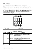

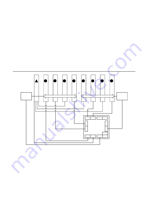
up to a Gen-2 x1 PCI Express, providing a maximum nominal single-direction bandwidth
of 500 MB/s (slots 2, 3, 5, 7, and 9).
•
A CompactPCI Express Type-2 Peripheral with x8, x4, or x1 PCI Express link to the
system slot or through a PCI Express switch or direct link to the system slot.
•
A hybrid-compatible PXI Peripheral module modified by replacing the J2 connector with
an XJ4 connector installed in the upper eight rows of J2. Refer to the
PXI Express
Specification
for details. The PXI peripheral communicates through the backplane’s 32-
bit PCI bus.
•
A CompactPCI 32-bit peripheral on the backplane’s 32-bit PCI bus.
The hybrid peripheral slots provide full PXI Express functionality and 32-bit PXI functionality
except for PXI Local Bus. The hybrid peripheral slot connects to only PXI Local Bus 6 left
and right.
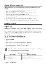
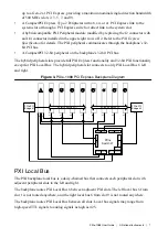
Figure 3. PXIe-1088 PCI Express Backplane Diagram
x4
x4
x4
x4
x1
x1
x1
x4
x4
x1
x1
x1
x1
x4
Port 15
Port 5 Port 7
Port 1
Port 14
Po
rt 3
Po
rt 9
Po
rt 12
Po
rt 10
Port 2 Port 0
PCIe
Switch #1
Port 13
Port 11
9
H
8
H
7
H
1
6
H
5
H
4
H
3
H
2
H
32-bit, 33 MHz PCI
32-bit, 33 MHz PCI
PCIe-PCI
Bridge #1
PCIe-PCI
Bridge #2
PXI Local Bus
The PXI backplane local bus is a daisy-chained bus that connects each peripheral slot with
adjacent peripheral slots to the left and right.
The backplane routes PXI Local Bus 6 between adjacent PXI slots. The left local bus 6 from
slot 1 is not routed anywhere, and the right local bus 6 from slot 9 is not routed anywhere.
The backplane routes PXI Local Bus between all slots. Local bus signals may range from
high-speed TTL signals to analog signals as high as 42 V.
PXIe-1088 User Guide
|
© National Instruments
|
7