© National Instruments
|
1-13
3.
Configure the IP and other network settings in MAX from the host computer.
4.
Move the IP RESET DIP switch to the OFF position.
Figure 1-6.
IP RESET DIP Switch in OFF Position
For more information about troubleshooting network communication, refer to the
MAX Remote
Systems Help
topic in the
Measurement & Automation Explorer Help
.
Wiring Power to the cDAQ Chassis
The cDAQ chassis requires an external power source as described in the
Power Requirements
section of the specifications document for your cDAQ chassis. Some suggested NI power
supplies are listed in Table 1-9. The cDAQ chassis filters and regulates the supplied power and
provides power to all of the I/O modules. The cDAQ chassis has a primary power input, V1, and
a secondary power input, V2. The POWER LED on the front panel identifies the power input in
use. When the LED is lit green, V1 is in use; when the LED is lit yellow, V2 is in use.
Caution
Do
not
connect V2 to a DC mains supply or to any supply requiring a
connecting cable longer than 3 m (10 ft). A DC mains supply is a local DC electricity
supply network in the infrastructure of a site or building.
Complete the following steps to connect a power source to the cDAQ chassis.
1.
Make sure the power source is turned off.
2.
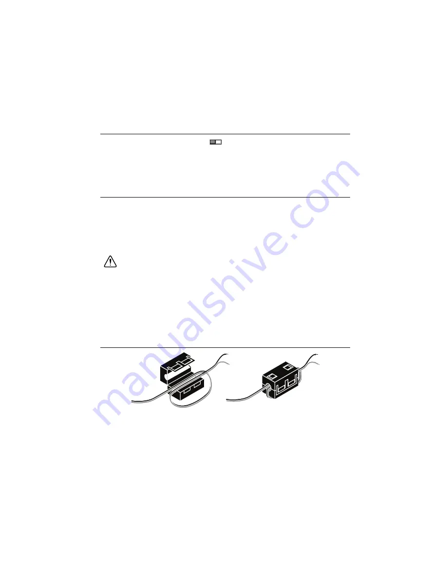
Install the ferrite shipped with the cDAQ chassis across the negative and positive leads of
the power source, approximately 50 to 75 mm (2 to 3 in.) from the ends of the leads near
the cDAQ chassis, as shown in Figure 1-7.
Figure 1-7.
Installing the Ferrite on the Power Leads
3.
Loosen the connector screws and remove the power screw terminal connector plug from
the cDAQ chassis. Figure 1-8 shows the terminal screws, which secure the wires in the
screw terminals, and the connector screws, which secure the connector plug on the front
panel.
IP RESET
ON
OFF


