5-26
|
ni.com
Chapter 5
Counters
Figure 5-28.
Finite Pulse Train Generation: Four Ticks Initial Delay, Four Pulses
Retriggerable Pulse or Pulse Train Generation
The counter can output a single pulse or multiple pulses in response to each pulse on a hardware
Start Trigger signal. The generated pulses appear on the Counter
n
Internal Output signal of the
counter.
You can route the Start Trigger signal to the Gate input of the counter. You can specify a delay
from the Start Trigger to the beginning of each pulse. You also can specify the pulse width.
The delay and pulse width are measured in terms of a number of active edges of the Source
input. The initial delay can be applied to only the first trigger or to all triggers using the
CO.EnableInitalDelayOnRetrigger
property. The default for a single pulse is True, while
the default for finite pulse trains is False.
The counter ignores the Gate input while a pulse generation is in progress. After the pulse
generation is finished, the counter waits for another Start Trigger signal to begin another pulse
generation. For retriggered pulse generation, pause triggers are not allowed since the pause
trigger also uses the gate input.
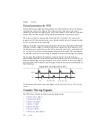
Figure 5-29 shows a generation of two pulses with a pulse delay of five and a pulse width of
three (using the rising edge of Source) with
CO.EnableInitalDelayOnRetrigge
r set to the
default True.
Figure 5-29.
Retriggerable Single Pulse Generation with Initial Delay on Retrigger
En
ab
le
x
S
o
u
rce
Ctr
x
Co
u
nter Armed
S
OURCE
GATE
(
S
t
a
rt Trigger)
OUT
5
3
5
3
Co
u
nter
Lo
a
d V
a
l
u
e
s
4
3
2 1 0 2 1 0
4
3
2
1
0 2 1
0


