


© National Instruments
|
5-23
NI cDAQ-9181/9184/9188/9191 User Manual
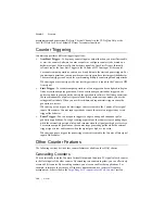
the count in the FIFO. On the next active edge of the Gate signal, the counter begins another
measurement. The STC3 transfers the sampled values to host memory using a high-speed data
stream.
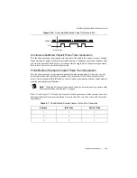
Figure 5-24 shows an example of an implicit buffered two-signal edge-separation measurement.
Figure 5-24.
Implicit Buffered Two-Signal Edge-Separation Measurement
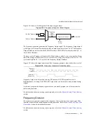
Sample Clocked Buffered Two-Signal Separation Measurement
A sample clocked buffered two-signal separation measurement is similar to single two-signal
separation measurement, but buffered two-signal separation measurement takes measurements
over multiple intervals correlated to a sample clock. The counter counts the number of rising (or
falling) edges on the Source input occurring between an active edge of the Gate signal and an
active edge of the Aux signal. The counter then stores the count in the FIFO on a sample clock
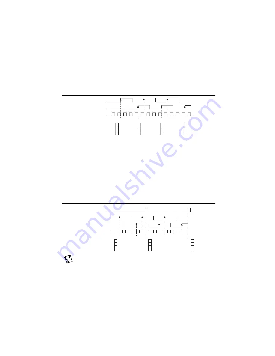
edge. On the next active edge of the Gate signal, the counter begins another measurement. The
STC3 transfers the sampled values to host memory using a high-speed data stream.
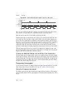
Figure 5-25 shows an example of a sample clocked buffered two-signal separation
measurement.
Figure 5-25.
Sample Clocked Buffered Two-Signal Separation Measurement
Note
If an active edge on the Gate and an active edge on the Aux do not occur
between sample clocks, an overrun error occurs.
For information about connecting counter signals, refer to the
section.
S
OURCE
Co
u
nter V
a
l
u
e
B
u
ffer
AUX
GATE
1
2
3
1
2
3
1
2
3
3
3
3
3
3
3
S
OURCE
Co
u
nter V
a
l
u
e
B
u
ffer
AUX
GATE
1
2
3
1
2
3
1
2
3
3
3
3
Sa
mple
Clock


