©
National Instruments Corp.
7
NI 9475 Operating Instructions and Specifications
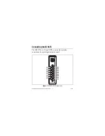
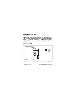
Each channel of the NI 9475 has a DO pin to which yo
u
can
connect a device. Each channel also has a COM pin and a V
s
u
p
pin.
National Instr
u
ments recommends yo
u
provide independent COM
and V
s
u
p
wiring for each channel to minimize c
u
rrent flow in the
COM and V
s
u
p
wiring. The COM pins are all connected together
internally.
Each channel has an LED that indicates the state of the channel.
When a channel LED is lit, the channel is on. When the LED is
dark, the channel is off.
Yo
u
m
u
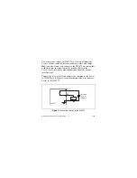
st connect an external power s
u
pply to the NI 9475. This
power s
u
pply provides the c
u
rrent for the devices yo
u
connect to
the mod
u
le. Connect the positive lead of the power s
u
pply to V
s
u
p
and the negative lead of the power s
u
pply to COM. Refer to the
section for information abo
u
t the power s
u
pply
voltage range.
Caution
Do not remove or insert mod
u
les if the external
power s
u
pply connected to the V
s
u
p
and COM pins is
powered on.
The NI 9475 has c
u
rrent so
u
rcing o
u
tp
u
ts, meaning the DO pin is
driven to V
s
u
p
when the channel is t
u
rned on.

