©
National Instruments Corp.
7
NI 9233 Operating Instructions and Specifications
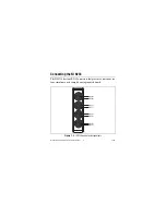
Each channel has a BNC connector to which yo
u
can connect an
Integrated Electronic Piezoelectric (IEPE) sensor. The center pin
of the connector, AI+, provides the DC excitation and the AC
signal connection. The shell of the connector, AI–, provides the
excitation ret
u
rn path and the AC signal gro
u
nd reference.
Yo
u
can connect gro
u
nd-referenced or floating IEPE sensors to the
NI 9233. Yo
u
can avoid picking
u
p gro
u
nd noise by
u
sing a floating
connection. Typical IEPE sensors have a case that is electrically
isolated from the IEPE electronics, so connecting the sensor to the
NI 9233 res
u
lts in a floating connection even tho
u
gh the case of the
sensor is gro
u
nded. To f
u
rther minimize gro
u
nd noise, prevent
the metal shells of the BNC connectors from to
u
ching each other,
the mod
u
les, or the chassis.
If yo
u
make a gro
u
nd-referenced connection between the IEPE
sensor and the NI 9233, make s
u
re the voltage on the AI– shell
is in the common-mode range to ens
u
re proper operation of the
NI 9233. The AI– shell is protected against accidental contact
with overvoltages within the overvoltage protection range. Refer
to the
section for more information abo
u
t operating
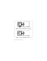
voltages and overvoltage protection. Fig
u
res 2 and 3 ill
u
strate
connecting gro
u
nded and floating IEPE sensors to the NI 9233.

