OPERATING INSTRUCTIONS AND SPECIFICATIONS
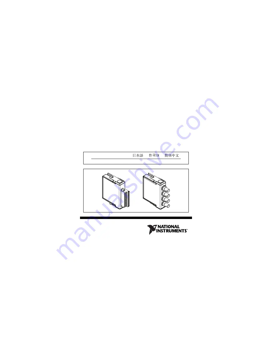
NI 9215
4-Channel, ±10 V, 16-Bit Simultaneous Analog Input Module
ni.com/manuals
Deutsch
Français
Страница 1: ...OPERATING INSTRUCTIONS AND SPECIFICATIONS NI 9215 4 Channel 10 V 16 Bit Simultaneous Analog Input Module ni com manuals Deutsch Français ...
Страница 2: ...ing configuring and programming the system refer to the system documentation Visit ni com info and enter cseriesdoc for information about C Series documentation Note The safety guidelines and specifications in this document are specific to the NI 9215 The other components in the system might not meet the same safety ratings and specifications Refer to the documentation for each component in the sy...
Страница 3: ...voltages are connected to the module take the following precautions A hazardous voltage is a voltage greater than 42 4 Vpk or 60 VDC to earth ground Caution Ensure that hazardous voltage wiring is performed only by qualified personnel adhering to local electrical standards Caution Do not mix hazardous voltage circuits and human accessible circuits on the same module Caution Make sure that devices ...
Страница 4: ...erly insulated from human contact You must use the NI 9932 connector backshell kit to ensure that the terminals are not accessible Figure 1 shows the NI 9932 connector backshell Note You can use the NI 9932 connector backshell only with the NI 9215 with screw terminal Figure 1 NI 9932 Connector Backshell ...
Страница 5: ...the NI 9215 in a potentially explosive environment Not following these guidelines may result in serious injury or death Caution Do not disconnect I O side wires or connectors unless power has been switched off or the area is known to be nonhazardous Caution Do not remove modules unless power has been switched off or the area is known to be nonhazardous Caution Substitution of components may impair...
Страница 6: ... is marked II 3G and is suitable for use in Zone 2 hazardous locations If you are using the NI 9215 in Gas Group IIC hazardous locations or in ambient temperatures of 40 C Ta 70 C you must use the device in an NI chassis that has been evaluated as Ex nA IIC T4 equipment Special Conditions for Marine Applications Some modules are Lloyd s Register LR Type Approved for marine applications To verify L...
Страница 7: ...or marine applications use shielded cables and install the system in a metal enclosure Suppression ferrites must be installed on power supply inputs near power entries to modules and controllers Power supply and module cables must be separated on opposite sides of the enclosure and must enter and exit through opposing enclosure walls ...
Страница 8: ...fications 8 ni com Connecting the NI 9215 The NI 9215 provides connections for four differential analog input channels Figure 2 Terminal Assignments of the NI 9215 with Screw Terminal 0 1 2 3 4 5 6 7 8 9 AI0 AI0 AI1 AI1 AI2 AI2 AI3 AI3 NC COM ...
Страница 9: ... National Instruments Corp 9 NI 9215 Operating Instructions and Specifications Figure 3 Connector Assignments of the NI 9215 with BNC AI3 AI3 AI2 AI2 AI0 AI0 AI1 AI1 ...
Страница 10: ... or shield to which you can connect the positive voltage signal and an AI terminal or shield to which you can connect the negative voltage signal The NI 9215 with screw terminal also has a common terminal COM that is internally connected to the isolated ground reference of the module Note You must use 2 wire ferrules to create a secure connection when connecting more than one wire to a single term...
Страница 11: ...the NI 9215 Connect the positive voltage signal to AI and the negative voltage signal to AI To connect grounded differential signals to the NI 9215 with screw terminal you must also connect the signal reference to the COM terminal as shown in Figure 4 Figure 4 Connecting a Grounded Differential Voltage Signal to the NI 9215 with Screw Terminal Voltage Source AI AI COM NI 9215 with Screw Terminal ...
Страница 12: ...as shown in Figure 5 If the voltage source is outside of the common mode range then the NI 9215 does not read data accurately The NI 9215 with BNC has internal circuitry that keeps the voltage source within the common mode range For more information about the common mode voltage range refer to the Specifications section Figure 5 Connecting a Floating Differential Voltage Signal to the NI 9215 with...
Страница 13: ...15 with screw terminal you must also connect the ground signal to the COM terminal to keep the common mode voltage in the specified range as shown in Figure 6 For more information about the common mode voltage range refer to the Specifications section Figure 6 Connecting a Single Ended Voltage Signal to the NI 9215 with Screw Terminal AI AI COM Voltage Source NI 9215 with Screw Terminal ...
Страница 14: ... National Instruments recommends that you either use ferrules to terminate wires to the detachable screw terminal connector or use the NI 9932 backshell kit to protect the connections Refer to Figure 7 for an illustration of using ferrules Refer to Figure 1 for an illustration of the NI 9932 connector backshell Figure 7 10 Terminal Detachable Screw Terminal Connector with a Ferrule ...
Страница 15: ...e information about overvoltage protection refer to the Specifications section The incoming analog signal on each channel is buffered and conditioned by the instrumentation amplifier and is then sampled by a 16 bit ADC The channels have independent track and hold amplifiers that allow you to sample all four channels simultaneously Refer to Figures 8 and 9 for input circuitry illustrations of the N...
Страница 16: ...ns and Specifications 16 ni com Figure 8 Input Circuitry for One Channel on the NI 9215 with Screw Terminal COM AI AI NI 9215 with Screw Terminal Isolated ADC Overvoltage Protection Overvoltage Protection Instrumentation Amplifier ...
Страница 17: ... 9215 with BNC has a resistor that ensures the input voltage does not drift outside of the common mode range Figure 9 Input Circuitry for One Channel on the NI 9215 with BNC AI AI Isolated ADC NI 9215 with BNC Instrumentation Amplifier 100 kΩ Overvoltage Protection Overvoltage Protection ...
Страница 18: ...mode If the chassis supports sleep mode refer to the software help for information about enabling sleep mode Visit ni com info and enter cseriesdoc for information about C Series documentation Typically when a system is in sleep mode you cannot communicate with the modules In sleep mode the system consumes minimal power and may dissipate less heat than it does in normal mode Refer to the Specifica...
Страница 19: ...ifications Specifications The following specifications are typical for the range 40 to 70 C unless otherwise noted Input Characteristics Number of channels 4 analog input channels ADC resolution 16 bits Type of ADC Successive approximation register SAR Input range 10 0 V ...
Страница 20: ...ting voltages Measurement Voltage AI to AI Maximum Voltage Signal Common Mode Minimum V Typical V Maximum V Screw Terminal BNC 10 2 10 4 10 6 Each channel must remain within 10 2 V of common All inputs must remain within 10 2 V of the average AI inputs The minimum measurement voltage range is the largest voltage the NI 9215 is guaranteed to accurately measure ...
Страница 21: ...6 μs Channels 0 1 and 2 8 μs Channels 0 1 2 and 3 10 μs Accuracy Stability Gain drift 10 ppm ºC Offset drift 60 μV ºC Measurement Conditions Percent of Reading Gain Error Percent of Range Offset Error Calibrated max 40 to 70 C 0 2 0 082 Calibrated typ 25 C 5 C 0 02 0 014 Uncalibrated max 40 to 70 C 1 05 0 82 Uncalibrated typ 25 C 5 C 0 6 0 38 Range equals 10 4 V ...
Страница 22: ... 3 dB 420 kHz min Input impedance Resistance NI 9215 with screw terminal 1 GΩ NI 9215 with BNC Between any two AI terminals 200 kΩ Input bias current 10 nA Input noise RMS 1 2 LSBrms Peak to peak 7 LSB Crosstalk 80 dB Settling time to 2 LSBs NI 9215 with screw terminal 10 V step 10 μs 20 V step 15 μs ...
Страница 23: ...ranteed DNL 1 9 to 2 LSB max INL 6 LSB max MTBF 1 167 174 hours at 25 C Bellcore Issue 6 Method 1 Case 3 Limited Part Stress Method Note Contact NI for Bellcore MTBF specifications at other temperatures or for MIL HDBK 217F specifications Power Requirements Power consumption from chassis full scale input 100 kS s Active mode 560 mW max Sleep mode 25 μW max ...
Страница 24: ...acteristics If you need to clean the module wipe it with a dry towel Screw terminal wiring 12 to 24 AWG copper conductor wire with 10 mm 0 39 in of insulation stripped from the end Torque for screw terminals 0 5 to 0 6 N m 4 4 to 5 3 lb in Ferrules 0 25 mm2 to 2 5 mm2 Weight NI 9215 with screw terminal 150 g 5 3 oz NI 9215 with BNC 173 g 6 1 oz ...
Страница 25: ...el No isolation between channels Channel to earth ground Continuous 250 Vrms Measurement Category II Withstand 2 300 Vrms verified by a 5 s dielectric withstand test Measurement Category II is for measurements performed on circuits directly connected to the electrical distribution system This category refers to local level electrical distribution such as that provided by a standard wall outlet for...
Страница 26: ...o isolation between channels Channel to earth ground Continuous 60 VDC Measurement Category I Withstand 1 500 Vrms verified by a 5 s dielectric withstand test Measurement Category I is for measurements performed on circuits not directly connected to the electrical distribution system referred to as MAINS voltage MAINS is a hazardous live electrical supply system that powers equipment This category...
Страница 27: ...ents within Measurement Categories II III or IV Safety Standards This product is designed to meet the requirements of the following standards of safety for electrical equipment for measurement control and laboratory use IEC 61010 1 EN 61010 1 UL 61010 1 CSA 61010 1 Note For UL and other safety certifications refer to the product label or visit ni com certification search by module number or produc...
Страница 28: ... T4 Europe DEMKO EEx nC IIC T4 Environmental National Instruments C Series modules are intended for indoor use only but may be used outdoors if installed in a suitable enclosure Refer to the manual for the chassis you are using for more information about meeting these specifications Operating temperature IEC 60068 2 1 IEC 60068 2 2 40 to 70 C Storage temperature IEC 60068 2 1 IEC 60068 2 2 40 to 8...
Страница 29: ... and Vibration To meet these specifications you must panel mount the system If you are using the NI 9215 with screw terminal you must also either affix ferrules to the ends of the terminal wires or use the NI 9932 backshell kit to protect the connections Operating vibration Random IEC 60068 2 34 5 grms 10 to 500 Hz Sinusoidal IEC 60068 2 6 5 g 10 to 500 Hz Operating shock IEC 60068 2 27 30 g 11 ms...
Страница 30: ...p 1 Class A CE C Tick ICES and FCC Part 15 Emissions Class A Note For EMC compliance operate this device with shielded cabling CE Compliance This product meets the essential requirements of applicable European directives as amended for CE markings as follows 2006 95 EC Low Voltage Directive safety 2004 108 EC Electromagnetic Compatibility Directive EMC Note Refer to the Declaration of Conformity D...
Страница 31: ...roducts is beneficial not only to the environment but also to NI customers For additional environmental information refer to the NI and the Environment Web page at ni com environment This page contains the environmental regulations and directives with which NI complies as well as other environmental information not included in this document Waste Electrical and Electronic Equipment WEEE EU Custome...
Страница 32: ... support At ni com support you have access to everything from troubleshooting and application development self help resources to email and phone assistance from NI Application Engineers National Instruments corporate headquarters is located at 11500 North Mopac Expressway Austin Texas 78759 3504 ᄤֵᙃѻક ᶧ ࠊㅵ ࡲ Ё RoHS Ё ᅶ National Instruments ヺড়Ё ᄤֵᙃ ѻકЁ䰤ࠊՓ ᶤѯ ᆇ 䋼ᣛҸ RoHS DŽ Ѣ National Instruments Ё Ro...
Страница 33: ...488 China 86 21 5050 9800 Czech Republic 420 224 235 774 Denmark 45 45 76 26 00 Finland 358 0 9 725 72511 France 01 57 66 24 24 Germany 49 89 7413130 India 91 80 41190000 Israel 972 3 6393737 Italy 39 02 413091 Japan 0120 527196 Korea 82 02 3451 3400 Lebanon 961 0 1 33 28 28 Malaysia 1800 887710 Mexico 01 800 010 0793 Netherlands 31 0 348 433 466 New Zealand 0800 553 322 Norway 47 0 66 90 76 60 Po...
Страница 34: ...to the Terms of Use section on ni com legal for more information about National Instruments trademarks Other product and company names mentioned herein are trademarks or trade names of their respective companies For patents covering National Instruments products refer to the appropriate location Help Patents in your software the patents txt file on your CD or ni com patents ...