1-2
|
ni.com
Chapter 1
NI 651x Fundamentals
If the DAQ device does not appear in MAX, use the following troubleshooting guidelines.
•
Verify that you are using the correct version of NI-DAQ (NI-DAQ 7.3 or later). To
download the most recent National Instruments drivers, go to
ni.com/drivers
.
•
Press <F5> to refresh the MAX window, or close and re-open MAX.
•
Reboot the computer.
•
Power off and unplug the computer or chassis, and install the device in a different slot.
Refer to the
DAQ Getting Started Guide
for installation instructions and safety guidelines.
NI 651
x
Functional Overview
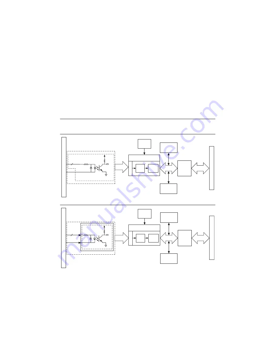
The following block diagrams illustrate the key functional components of the NI 651
x
devices.
Figure 1-1.
NI 6510 Block Diagram
Figure 1-2.
NI 6511 Block Diagram
PCI B
us
Ind
us
tri
a
l Digit
a
l
Inp
u
t Control FPGA
Inp
u
t Line
s
Ch
a
nge
Detection
Digit
a
l
Filtering
D
a
t
a
/Control
PCI B
us
Interf
a
ce
D
a
t
a
/Control
Fl
as
h
Memory
Config
u
r
a
tion
Control
I/O Connector
3
2
COM
PX.<0..7>
VCC
x
3
2 B
a
nk I
s
ol
a
ted Inp
u
t Ch
a
nnel
s
DI
10 MHz
Clock
3
2 Digit
a
l
Inp
u
t
s
I/O Connector
PCI/PXI/Comp
a
ctPCI B
us
Ind
us
tri
a
l Digit
a
l
Inp
u
t Control FPGA
Inp
u
t Line
s
Ch
a
nge
Detection
Digit
a
l
Filtering
D
a
t
a
/Control
PCI B
us
Interf
a
ce
D
a
t
a
/Control
Fl
as
h
Memory
Config
u
r
a
tion
Control
8
PX.COM
PX.<0..7>
Vcc
x8 B
a
nk I
s
ol
a
ted Digit
a
l Inp
u
t Port
s
x8 Inp
u
t
s
per Port
DI
10 MHz
Clock
64 Digit
a
l
Inp
u
t
s


