


Power On Your Computer or PXI Chassis
Windows recognizes any newly installed device the first time you restart the computer after hardware
is installed. On some Windows systems, the Found New Hardware wizard opens with a dialog box for
every NI device installed.
Install the software automatically (Recommended)
is selected by default.
Click
Next
or
Yes
to install the software for each device.
•
PXI or PXI Express devices controlled using MXI—Power the PXI chassis before you power on
the PC.
•
PCI devices—Verify that spread-spectrum clocking is enabled in the PC BIOS. Refer to the PC
user documentation for information about how to verify this setting if it is available.
Caution
Spread-spectrum clocking varies the clock signal to spread the timing clock signal
over a small frequency range. Disabling spread-spectrum clocking may affect the accuracy
of the signal generator specifications.
Configuring and Testing in MAX
Complete the following steps to configure and test your device:
1.
Launch MAX.
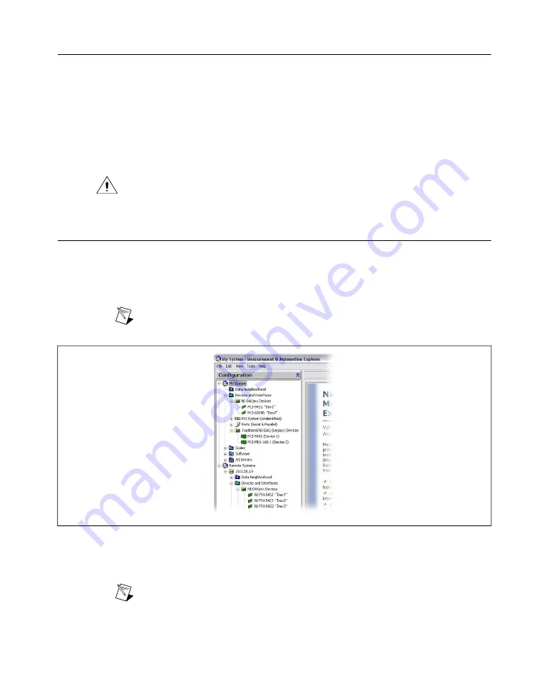
2.
In the configuration pane, double-click
Devices and Interfaces
and expand the
NI-DAQmx Devices
folder.
Note
If you are using a remote RT target, expand
Remote Systems
, find and expand
your target, and then expand
Devices and Interfaces
.
Figure 3. MAX Configuration Pane
3.
Check that your device appears under
Devices and Interfaces
. If your device does not appear,
press <F5> to refresh the view in MAX. If the device is still not recognized, refer to
.
Note
If you are using a MXI interface to control a PXI or PXI Express chassis and
encounter performance or initialization issues, refer to your MXI documentation to verify
the system requirements and to ensure that the MXI interface is properly configured.
Software optimization might be necessary. For MXI-3 optimization, select
Start
»
All
©
National Instruments Corporation
9
NI Signal Generators Getting Started Guide


