manualshive.com logo in svg
background image

c.

On the calibrator, lock the voltage range to 3.3 V to reduce loading error.

d.

Set the calibrator to the first reference value determined by the array of adjustment
points.

e.

Set the calibrator to Operate mode (OPR).

f.

Call and configure the DAQmx Adjust 11613 Calibration or DAQmx Adjust 11614
Calibration function according to the following table.

Table 7. Voltage Adjustment Configuration

Physical Channel

Reference Value


FD11613-Bank1/ai0:7 or
FD11614-Bank1/ai0:7

A reference value from the array of
adjustment points

g.

Set the calibrator to Standby mode (STBY).

h.

Repeat steps d through g for each reference value in the array of adjustment points.

4.

Disconnect the calibrator from the FieldDAQ device.

5.

(FD-11614)

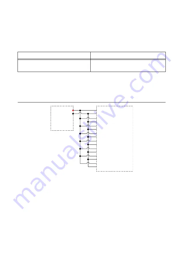
 Connect the calibrator to Bank 2 of the FD-11614, as shown in the following

figure.

Figure 4. Bank 2 Voltage Channel Adjustment Connections

TC0+

TC0–

HI

LO

TC1+

TC1–

TC6+

TC6–
TC7+

TC7–

Calibrator

FD-11614

TC2+

TC2–
TC3+

TC3–
TC4+

TC4–
TC5+

TC5–

Bank 2

6.

(FD-11614)

 Without closing the Bank 1 session, complete Steps 2 through 4 for Bank 2

using FD11614-Bank2/ai0:7 as the physical channel.

7.

(FD-11613)

 Close and commit the calibration session.

(FD-11614)

 Close and commit both calibration sessions.

EEPROM Update

When an adjustment procedure is completed, the FieldDAQ device internal calibration
memory (EEPROM) is immediately updated.

8

  | 

ni.com

  | 

FD-11613/11614 Calibration Procedure

Содержание FD-11613

Страница 1: ...to Go for Support 10 Software Requirements Calibrating the FD 11613 or FD 11614 requires the installation of NI DAQmx on the calibration system NI recommends using the latest NI DAQmx driver Earliest...

Страница 2: ...pplications that use the NI DAQmx driver NI DAQmx C Reference Help Reference information for NI DAQmx C functions and NI DAQmx C properties Test Equipment The following table lists the equipment requi...

Страница 3: ...rt Note You must install NI DAQmx 18 1 or later for device calibration support 2 Set up the FieldDAQ device as outlined in the FD 11613 11614 Quick Start 3 Configure the FieldDAQ device in Measurement...

Страница 4: ...of operation and test points required to verify the FieldDAQ device The verification procedures assume that adequate traceable uncertainties are available for the calibration references Complete the...

Страница 5: ...Accuracy Under Calibration Conditions 4 Set the calibrator to Operate mode OPR 5 Acquire and average samples a Create and configure an AI voltage channel on the FieldDAQ device according to the follow...

Страница 6: ...om each channel and average the readings e Clear the task 13 Compare the average to the limits in the following table Table 6 FD 11613 11614 Voltage Verification Test Limits for Zero Test Points ADC T...

Страница 7: ...eldDAQ device as shown in the following figure Figure 3 Bank 1 Voltage Channel Adjustment Connections TC0 TC0 HI LO TC1 TC1 TC6 TC6 TC7 TC7 Calibrator FD 11613 11614 TC2 TC2 TC3 TC3 TC4 TC4 TC5 TC5 Ba...

Страница 8: ...gh g for each reference value in the array of adjustment points 4 Disconnect the calibrator from the FieldDAQ device 5 FD 11614 Connect the calibrator to Bank 2 of the FD 11614 as shown in the followi...

Страница 9: ...onditions The values in the following table are based on calibrated scaling coefficients which are stored in the onboard EEPROM The following accuracy table is valid for calibration under the followin...

Страница 10: ...d Logo Guidelines at ni com trademarks for information on NI trademarks Other product and company names mentioned herein are trademarks or trade names of their respective companies For patents coverin...

Отзывы: