background image

12

|

ni.com

|

NI CVS-1459RT Getting Started Guide

Digital I/O

The 44-pin Digital I/O port on the NI CVS-1459RT offers 8 isolated inputs, 8 isolated outputs, 
2 bidirectional differential I/O (RS-422) or single-ended input lines which can be used with a 
quadrature encoder, and 8 bidirectional TTL lines. The Digital I/O port can be connected to any 
appropriate shielded device or connector block using a shielded cable. Refer to Table for pin 
locations and functions.
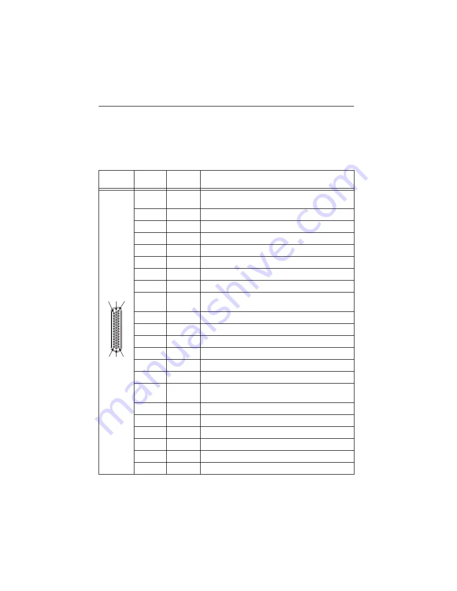
 

Table 1.  

Pin Location and Definition for the NI CVS-1459RT Digital I/O

Pin 

Location

Pin 

Number

S

ignal

De

s

cription

1

Diff 0+

Bidirectional RS-422 I/O (positive side), or quadrature 
encoder phase A+

2

GND

Digital ground reference for TTL and differential I/O

3

TTL 0

Bidirectional TTL I/O

4

TTL 1

Bidirectional TTL I/O

5

GND

Digital ground reference for TTL and differential I/O

6

TTL 2

Bidirectional TTL I/O

7

TTL 3

Bidirectional TTL I/O

8

GND

Digital ground reference for TTL and differential I/O

9

Diff 1+

Bidirectional RS-422 I/O (positive side), or quadrature 
encoder phase B+

10

V

ISO

Isolated power voltage reference output

11

C

ISO

Common ground reference for isolated inputs and outputs

12

Iso Out 0

General purpose isolated output

13

Iso Out 1

General purpose isolated output

14

C

ISO

Common ground reference for isolated inputs and outputs

15

Iso Out 4

General purpose isolated output

16

Diff 0-

Bidirectional RS-422 I/O (negative side), or quadrature 
encoder phase A-

17

GND

Digital ground reference for TTL and differential I/O

18

TTL 4

Bidirectional TTL I/O

19

TTL 5

Bidirectional TTL I/O

20

GND

Digital ground reference for TTL and differential I/O

21

TTL 6

Bidirectional TTL I/O

22

TTL 7

Bidirectional TTL I/O

15

3

0

44

1

16

3

1

Содержание CVS-1459RT

Страница 1: ...ling the Vision Development Module 5 Configuring the Hardware 6 Wiring Power to the NI CVS 1459RT 8 Connecting the System Power Supply 8 Connecting the Isolated Outputs Power Supply 8 Connecting USB3...

Страница 2: ...resulting in degraded network performance Development computer running Microsoft Windows Refer to the driver or application development software readme for specific Windows version compatibility A co...

Страница 3: ...ty of the NI CVS 1459RT in LabVIEW or to reconfigure the default personality of the NI CVS 1459RT I O in the LabVIEW FPGA Module Safety Information Caution The following paragraphs contain important s...

Страница 4: ...which the device is rated Do not exceed the maximum ratings for the device Remove power from signal lines before connection to or disconnection from the device Electromagnetic Compatibility Guideline...

Страница 5: ...e to develop applications and LabVIEW FPGA to reconfigure the I O The software must be installed in this order 1 LabVIEW Refer to the LabVIEW Installation Guide for installation instructions and syste...

Страница 6: ...equirements and installation instructions for the NI IMAQ I O driver Documentation for the NI IMAQ I O driver software is available by selecting Start All Programs National Instruments Vision Document...

Страница 7: ...2 System Power Connector 3 Isolated Outputs Power Connector 4 Chassis Grounding Screw 1 VGA Connector 2 RJ50 Serial Port 3 USB 2 0 Ports 4 RJ45 Network Port 5 USB3 Vision Ports 6 44 pin Digital I O Co...

Страница 8: ...N m 1 8 to 2 2 lb in of torque 4 Connect the negative lead of the power source to the C terminal of the power connector plug and tighten the terminal screw to 0 2 to 0 25 N m 1 8 to 2 2 lb in of torq...

Страница 9: ...onnect to the development computer directly or through a network To connect over a network the device must be on the same subnet as the development computer Direct Connection Complete the following st...

Страница 10: ...ble targets 3 Select the Configure Target icon 4 Complete the configuration wizard At step 3 select Update Target Software to install Vision Builder AI on the device Configuring the Device in NI MAX C...

Страница 11: ...of available targets 3 In the Configure Inspection section select New Inspection from Template 4 Select Acquire Image Template from the Compact Vision System tree 5 Click the Run Inspection Once icon...

Страница 12: ...TTL 1 Bidirectional TTL I O 5 GND Digital ground reference for TTL and differential I O 6 TTL 2 Bidirectional TTL I O 7 TTL 3 Bidirectional TTL I O 8 GND Digital ground reference for TTL and differen...

Страница 13: ...ral purpose isolated input 33 CISO Common ground reference for isolated inputs and outputs 34 Iso In 2 General purpose isolated input 35 Iso In 3 General purpose isolated input 36 CISO Common ground r...

Страница 14: ...n Builder AI inspections are installed to the Vision Builder AI Examples directory where Vision Builder AI is the location Vision Builder AI is installed Additional Resources for LabVIEW Users Documen...

Страница 15: ...ncil of the European Communities using the manufacturer s declaration of conformity This system affords the user protection for electromagnetic compatibility EMC and product safety You can obtain the...

Страница 16: ...s You can find information about end user license agreements EULAs and third party legal notices in the readme file for your NI product Refer to the Export Compliance Information at ni com legal expor...

Отзывы: