background image

© National Instruments

|

5-7

NI cDAQ-9132/9133/9134/9135/9136/9137 User Manual

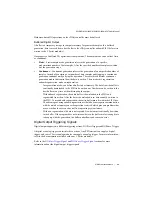
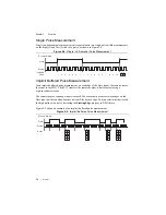
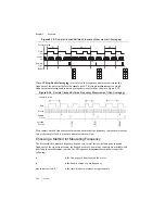
Figure 5-7 shows an example of a sample clocked buffered pulse-width measurement.

Figure 5-7.  

Sample Clocked Buffered Pulse-Width Measurement

Note

If a pulse does not occur between sample clocks, an overrun error occurs.

For information about connecting counter signals, refer to the 

Default Counter/Timer Routing


section.

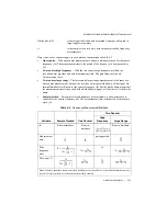
Pulse Measurement

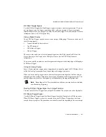
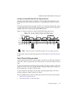
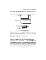
In pulse measurements, the counter measures the high and low time of a pulse on its Gate input 
signal after the counter is armed. A pulse is defined in terms of its high and low time, high and 
low ticks or frequency and duty cycle. This is similar to the pulse-width measurement, except 
that the inactive pulse is measured as well.

You can route an internal or external periodic clock signal (with a known period) to the Source 
input of the counter. The counter counts the number of rising (or falling) edges occurring on the 
Source input between two edges of the Gate signal.

You can calculate the high and low time of the Gate input by multiplying the period of the Source 
signal by the number of edges returned by the counter.

Refer to the following sections for more information about cDAQ controller pulse measurement 
options:

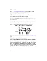
Single Pulse Measurement

Implicit Buffered Pulse Measurement

Sample Clocked Buffered Pulse Measurement

P

u

l

s

e

S

o

u

rce

Sa

mple Clock

2

3

4

2

4

3

2

2

4

B

u

ffer

Содержание cDAQ-9133

Страница 1: ...NI cDAQ TM 9132 9133 9134 9135 9136 9137 User Manual NI CompactDAQ Controller NI cDAQ 9132 9133 9134 9135 9136 9137 User Manual January 2019 371800E 01...

Страница 2: ...and current events National Instruments Corporate Headquarters 11500 North Mopac Expressway Austin Texas 78759 3504 USA Tel 512 683 0100 For further support information refer to the Technical Support...

Страница 3: ...ESS FOR A PARTICULAR PURPOSE TITLE OR NON INFRINGEMENT AND ANY WARRANTIES THAT MAY ARISE FROM USAGE OF TRADE OR COURSE OF DEALING NI DOES NOT WARRANT GUARANTEE OR MAKE ANY REPRESENTATIONS REGARDING TH...

Страница 4: ...es independent from National Instruments and have no agency partnership or joint venture relationship with National Instruments Patents For patents covering National Instruments products technology re...

Страница 5: ...om the cDAQ Controller 1 18 Mounting the cDAQ Controller 1 18 Mounting the cDAQ Controller on a Panel 1 21 Using the cDAQ Controller on a Desktop 1 24 Mounting the cDAQ Controller on a DIN Rail 1 26 M...

Страница 6: ...e Modules 2 4 AI Start Trigger Signal 2 4 Using a Digital Source 2 5 Using an Analog Source 2 5 Routing AI Start Trigger to an Output Terminal 2 5 AI Reference Trigger Signal 2 5 Using a Digital Sourc...

Страница 7: ...ers 4 6 Getting Started with DI Applications in Software 4 7 Change Detection Event 4 7 Routing Change Detection Event to an Output Terminal 4 7 Change Detection Acquisition 4 7 Digital Output 4 8 Dig...

Страница 8: ...1 Buffered Sample Clock Position Measurement 5 21 Two Signal Edge Separation Measurement 5 22 Single Two Signal Edge Separation Measurement 5 22 Implicit Buffered Two Signal Edge Separation Measuremen...

Страница 9: ...Counter n HW Arm Signal 5 35 Routing Signals to Counter n HW Arm Input 5 36 Counter n Sample Clock Signal 5 36 Using an Internal Source 5 36 Using an External Source 5 37 Routing Counter n Sample Cloc...

Страница 10: ...Contents x ni com Appendix A Controller Operating System and BIOS Configuration Appendix B Where to Go from Here Appendix C Technical Support and Professional Services Index...

Страница 11: ...ng started with the cDAQ controller with Windows and with LabVIEW Real Time For NI cDAQ 9132 9133 9134 9135 9136 9137 for Windows refer to the Installing the cDAQ Controller for Windows section For NI...

Страница 12: ...SER1 Button 10 SD Card Removable Storage and SD Card Slot Cover Mounting Holes 11 SD ACT and SD IN USE LEDs 12 RS 232 Serial Port 13 PFI 0 SMB Connector 14 Mini DisplayPort Connector 15 USB Host Ports...

Страница 13: ...restrictions Refer to the specifications document for your cDAQ controller for more details Hot Surface This icon denotes that the component may be hot Touching this component may result in bodily in...

Страница 14: ...oid your authority to operate it under your local regulatory rules Caution To ensure the specified EMC performance product installation requires either special considerations or user installed add on...

Страница 15: ...bol is marked on a product the product could be damaged if subjected to Electrostatic Discharge ESD on the connector pins of any I O port To prevent damage industry standard ESD prevention measures mu...

Страница 16: ...ged device in your computer or controller Store the device in the antistatic package when the device is not in use Installing the cDAQ Controller for Windows NI cDAQ 9132 9133 9134 9135 9136 9137 for...

Страница 17: ...ower on the monitor 4 Connect a computer keyboard and mouse to the USB host ports on the cDAQ controller Use one of the ferrites around both USB cables as described in the USB Host Ports section 5 Att...

Страница 18: ...epeat Steps 6 and 7 to install additional modules 8 Wire your external power source and install the remaining ferrite as outlined in the Wiring Power to the cDAQ Controller section The cDAQ controller...

Страница 19: ...ogging NI DAQmx Caution Removing power without shutting down the cDAQ controller can corrupt the embedded Windows system drive For information about how to improve robustness on the Windows system go...

Страница 20: ...ach cDAQ controller for LabVIEW for Real Time The NI DAQmx driver software is included on the media shipped with your kit and is available for download at ni com support The documentation for NI DAQmx...

Страница 21: ...Align the module with a cDAQ controller slot 9 Squeeze the latches and insert the module into the module slot and press firmly on the connector side of the module until the latches lock the module in...

Страница 22: ...ate reads Connected Safe Mode No Software Installed Figure 1 4 cDAQ Controller System Settings in MAX Note If you are connecting through the RJ 45 Ethernet port instead of the USB device port and cann...

Страница 23: ...NI cDAQ model number serial number Click the System Settings tab and verify that the System State reads Connected Running 23 Self test your controller in MAX by expanding NI cDAQ model number serial...

Страница 24: ...hernet installation do not use a cable longer than 100 m The cDAQ controller attempts to initiate a DHCP network connection at powerup If the cDAQ controller is unable to obtain an IP address it conne...

Страница 25: ...he same behavior The cDAQ controller attempts to establish a new DHCP connection If it fails it assigns itself a link local IP address If the DHCP connection is successful and appropriate for your app...

Страница 26: ...ew terminals and the connector screw flanges which secure the connector plug on the front panel Figure 1 7 Power Screw Terminal Connector Plug Caution Do not tighten or loosen the terminal screws on t...

Страница 27: ...he specifications document for your cDAQ controller for information about the maximum voltage from terminal to chassis ground Powering Down the cDAQ Controller There are two methods for safely powerin...

Страница 28: ...e Embedded UI to Access RT Target VIs topic in the LabVIEW Help Removing Modules from the cDAQ Controller Complete the following steps to remove a C Series module from the cDAQ controller 1 Make sure...

Страница 29: ...Measure the ambient temperature at each side of the controller 63 5 mm 2 5 in from the side and 38 1 mm 1 5 in forward from the rear of the controller as shown in Figures 1 10 and 1 11 For more infor...

Страница 30: ...LINK LINK ACT ACT LINK LINK NI cDAQ 9134 NI CompactDAQ 4 USER2 4 USER2 RESET RESET 3 USER1 3 USER1 1 1 2 3 4 2 STATUS 2 STATUS 1 POWER 1 POWER PUSH TO EJECT PUSH TO EJECT DO NOT SEPERATE CONNECTORS W...

Страница 31: ...Use M4 screws with a length suitable for the depth of the panel You can use the NI panel mount kit to mount the cDAQ controller on a flat surface Refer to the Cables and Accessories section for the ac...

Страница 32: ...th Mounting Plate Installed 1 The NI cDAQ 9132 9134 9136 controller panel mounting plate requires four screws The NI cDAQ 9133 9135 9137 controller panel mounting plate requires six screws 25 41 mm 1...

Страница 33: ...ally you can use two additional screws to attach the mounting plate to the panel or wall permanently preventing the controller from being removed Figure 1 15 Permanently Attaching the Mounting Plate t...

Страница 34: ...e End Brackets to the Controller cDAQ 9134 Shown 2 Use a number 2 Phillips screwdriver to tighten the captive screw on the end bracket 3 Repeat steps 1 and 2 to attach the other end bracket to the oth...

Страница 35: ...dimensions of a controller after the desktop mounting kit is installed Figure 1 17 Dimensions of the cDAQ 9132 9134 9136 with Desktop Mounting Kit Installed 252 37 mm 9 936 in 2x 17 23 mm 0 678 in 39...

Страница 36: ...omplete the following steps to mount the controller on a DIN rail 1 Fasten the DIN rail clip to the controller using a number 2 Phillips screwdriver and M4 10 screws1 National Instruments provides the...

Страница 37: ...DIN rail Figure 1 20 DIN Rail Clip Parts Locator Diagram Caution Remove the modules before removing the controller from the DIN rail Mounting the cDAQ Controller on a Rack NI offers two rack mount ki...

Страница 38: ...ry prior to mounting the system in any enclosure because the accessory requires tool access to the top right and bottom of the cDAQ controller What to use cDAQ controller C Series modules Module Immob...

Страница 39: ...bracket into place aligning the three clearance screw holes 4 Install the M4 0 7 button head screw in the right end of the cDAQ controller using the appropriate Torx T20 driver Tighten the screw to a...

Страница 40: ...to Figure 1 1 or 1 2 for the locations of these features on the cDAQ controller Mini DisplayPort Connector Use the mini DisplayPort connector shown in Figure 1 1 or 1 2 to connect a monitor to progra...

Страница 41: ...V W or X drive starting with the U drive if it is available You can also use these ports to connect a computer keyboard and mouse for controller programming Install a noise suppression ferrite Nation...

Страница 42: ...9135 9136 9137 for LabVIEW Real Time The USB device port shown in Figure 1 1 or 1 2 is intended for use in device configuration application deployment debug and maintenance For example you can instal...

Страница 43: ...etwork Communication in the LabVIEW Real Time Controller section Power Button The default behavior for the cDAQ controller is to power on when power is applied to the controller and power off by press...

Страница 44: ...ter 1 Getting Started with the cDAQ Controller LEDs The cDAQ controller features four LEDs POWER STATUS USER1 and USER2 on its front panel as shown in Figure 1 1 or 1 2 Table 1 6 lists the LEDs and st...

Страница 45: ...oller runs out of memory Review your RT VI and check the memory usage Modify the VI as necessary to solve the memory usage issue Continuously flashing The controller either booted into an unsupported...

Страница 46: ...ssover cable to connect to a host computer NI cDAQ 9132 9133 9134 9135 9136 9137 for Windows Both Ethernet ports are enabled and configured as DHCP to obtain an IP address automatically by default The...

Страница 47: ...ED LED Color LED State Indication ACT LINK Off LAN link not established Green Solid LAN link established Flashing Activity on LAN 10 100 1000 Yellow Solid 1 000 Mbit s data rate selected Green Solid 1...

Страница 48: ...duct performance and accuracy specifications when using the NI XNET CAN LIN port and NI transceiver cable s do not attach or mount the transceiver overmold directly to the cDAQ controller Mount the ov...

Страница 49: ...vices such as displays or input devices Use the Serial VIs to read from and write to the serial port Refer to the LabVIEW Help for information about the Serial VIs Refer to Figure 1 27 for pin locatio...

Страница 50: ...rd in hazardous locations Do not remove an SD card while either LED is flashing or lit because file corruption may result Caution Do not insert or remove SD cards unless power has been switched off or...

Страница 51: ...ng 1 31 mm2 16 AWG or larger wire Use shorter wire for better EMC performance CMOS Battery and CMOS Reset Button The cDAQ controller contains a CMOS battery a lithium cell battery that stores the syst...

Страница 52: ...essories and ordering information refer to the pricing section of the NI cDAQ 9132 9133 9134 9135 9136 9137 product page at ni com Caution To ensure the specified EMC performance operate this product...

Страница 53: ...and 10 m lengths 151733 02 151733 05 151733 10 All Cable Adapters for 10 position Modular Jacks 1 2 and 3 m lengths 182845 01 182845 02 182845 03 All SD Slot Covers x3 783660 01 All SD Industrial Sto...

Страница 54: ...lock Diagram Keyboard and Mouse 779660 01 All USB CD DVD Drive 778492 01 All NI TSM 1012 Touch Screen Monitor 12 in 783635 01 All NI TSM 1015 Touch Screen Monitor 15 in 783636 01 All NI TSM 1017 Touch...

Страница 55: ...is capable of measuring or generating Serial digital modules are designed for signals that change slowly and are accessed by either software timed or hardware timed reads and writes Parallel digital...

Страница 56: ...access to advanced features such as triggering synchronization and counter timers You can also enable a programmable debouncing filter on each PFI signal that when enabled samples the input on each r...

Страница 57: ...ut Triggering Signals A trigger is a signal that causes an action such as starting or stopping the acquisition of data When you configure a trigger you must decide how you want to produce the trigger...

Страница 58: ...n Output Terminal You can route Sample Clock to any output PFI terminal Sample Clock is an active high pulse by default AI Sample Clock Timebase Signal The AI Sample Clock Timebase signal is divided d...

Страница 59: ...n every Sample Clock pulse Sigma Delta Modules Sigma delta C Series analog input modules function much like SSH modules but use ADCs that require a high frequency oversample clock to produce accurate...

Страница 60: ...For example if running an AI task at 1 kHz using a module with a maximum rate of 10 Hz the slow module returns 100 samples of the first point followed by 100 samples of the second point etc Other modu...

Страница 61: ...nding on the C Series module capabilities you may need two modules to utilize analog triggering Routing AI Start Trigger to an Output Terminal You can route the Start Trigger signal to any output PFI...

Страница 62: ...oller can provide the source Refer to the Device Routing in MAX topic in the NI DAQmx Help or the LabVIEW Help for more information Using an Analog Source Some C Series modules can generate a trigger...

Страница 63: ...ing an Analog Source Some C Series modules can generate a trigger based on an analog signal In NI DAQmx this is called the Analog Comparison Event When you use an analog trigger source the internal sa...

Страница 64: ...ethods When performing an analog output operation you either can perform software timed or hardware timed generations Hardware timed generations must be buffered Software Timed Generations With a soft...

Страница 65: ...ing a continuous generation continues until you stop the operation There are three different continuous generation modes that control how the data is written These modes are regeneration onboard regen...

Страница 66: ...t Timing Signals The cDAQ controller features the following AO waveform generation timing signals AO Sample Clock Signal AO Sample Clock Timebase Signal AO Start Trigger Signal AO Pause Trigger Signal...

Страница 67: ...er specify a source and a rising or falling edge The source can be one of the following signals A pulse initiated by host software Any PFI terminal AI Reference Trigger AI Start Trigger The source als...

Страница 68: ...ock the generation resumes as soon as the pause trigger is deasserted as shown in Figure 3 2 Figure 3 2 AO Pause Trigger with the Onboard Clock Source If you are using any signal other than the onboar...

Страница 69: ...a DAC to generate a waveform you may observe glitches on the output signal These glitches are normal When a DAC switches from one voltage to another it produces glitches due to released charges The la...

Страница 70: ...timed and hardware timed digital input output tasks Parallel digital modules can be used in any controller slot and can perform the following tasks Software timed and hardware timed digital input outp...

Страница 71: ...es of digital triggering internal software digital triggering external digital triggering and internal digital triggering Three triggers are available Start Trigger Reference Trigger and Pause Trigger...

Страница 72: ...s an active high pulse by default DI Sample Clock Timebase Signal The DI Sample Clock Timebase di SampleClockTimebase signal is divided down to provide a source for DI Sample Clock DI Sample Clock Tim...

Страница 73: ...mples are measured only after the trigger When you are using an internal sample clock you can specify a delay from the start trigger to the first sample Using a Digital Source To use DI Start Trigger...

Страница 74: ...can be accessed with some limitations before the cDAQ controller discards it Refer to the KnowledgeBase document Can a Pretriggered Acquisition be Continuous for more information To access this Knowl...

Страница 75: ...NI DAQmx Help or the LabVIEW Help for more information Using an Analog Source Some C Series modules can generate a trigger based on an analog signal In NI DAQmx this is called the Analog Comparison Ev...

Страница 76: ...pplications in Software You can use the cDAQ controller in the following digital input applications Single point acquisition Finite acquisition Continuous acquisition Change Detection Event The Change...

Страница 77: ...imed tasks You may have a hardware timed task or a software timed task include channels from multiple modules but a hardware timed task may not include a mix of channels from both parallel and serial...

Страница 78: ...oaded to the FIFO to be written out New data can be written to the host buffer at any time without disrupting the output With onboard regeneration the entire buffer is downloaded to the FIFO and regen...

Страница 79: ...rnal or internal sources as shown in Figure 4 4 Figure 4 4 Digital Output Timing Options Routing DO Sample Clock to an Output Terminal You can route DO Sample Clock to any output PFI terminal DO Sampl...

Страница 80: ...eneration begins on the rising edge or falling edge of DO Start Trigger Using an Analog Source Some C Series modules can generate a trigger based on an analog signal In NI DAQmx this is called the Ana...

Страница 81: ...olarity The source can be a PFI signal or one of several other internal signals on the cDAQ controller You also can specify whether the samples are paused when DO Pause Trigger is at a logic high or l...

Страница 82: ...output lines are maintained without glitching PFI You can configure channels of a parallel digital module as Programmable Function Interface PFI terminals The cDAQ controller also provides one termin...

Страница 83: ...n on an input that has a custom filter set to N 5 Figure 4 7 PFI Filter Example Table 4 1 Selectable PFI Filter Settings Filter Setting Filter Clock Jitter Min Pulse Width to Pass Max Pulse Width to N...

Страница 84: ...cting counter signals refer to the Default Counter Timer Routing section Each counter has a FIFO that can be used for buffered acquisition and generation Each counter also contains an embedded counter...

Страница 85: ...rison Event Not all timed counter operations require a sample clock For example a simple buffered pulse width measurement latches in data on each edge of a pulse For this measurement the measured sign...

Страница 86: ...g section The counter values can be read on demand or with a sample clock Refer to the following sections for more information about edge counting options Single Point On Demand Edge Counting Buffered...

Страница 87: ...the number of edges on the Source input after the counter is armed The value of the counter is sampled on each active edge of a sample clock and stored in the FIFO The STC3 transfers the sampled valu...

Страница 88: ...ling edges on the Source signal while the pulse on the Gate signal is active You can calculate the pulse width by multiplying the period of the Source signal by the number of edges returned by the cou...

Страница 89: ...a high speed data stream Figure 5 6 shows an example of an implicit buffered pulse width measurement Figure 5 6 Implicit Buffered Pulse Width Measurement Sample Clocked Buffered Pulse Width Measureme...

Страница 90: ...high and low ticks or frequency and duty cycle This is similar to the pulse width measurement except that the inactive pulse is measured as well You can route an internal or external periodic clock s...

Страница 91: ...s the sampled values to host memory using a high speed data stream The counter begins counting when it is armed The arm usually occurs between edges on the Gate input but the counting does not start u...

Страница 92: ...ccurs For information about connecting counter signals refer to the Default Counter Timer Routing section Semi Period Measurement In semi period measurements the counter measures a semi period on its...

Страница 93: ...Semi Period Measurement For information about connecting counter signals refer to the Default Counter Timer Routing section Pulse versus Semi Period Measurements In hardware pulse measurement and sem...

Страница 94: ...measurements with one counter you measure one period of your signal using a known timebase You can route the signal to measure fx to the Gate of a counter You can route a known timebase fk to the Sour...

Страница 95: ...you measure the width of pulse T to be N periods of fx the frequency of fx is N T Figure 5 13 illustrates this method Another option is to measure the width of a known period instead of a known pulse...

Страница 96: ...is given by fx fk N J Sample Clocked Buffered Frequency Measurement Sample clocked buffered point frequency measurements can either be a single frequency measurement or an average between sample clock...

Страница 97: ...fast as the sample clock to prevent a measurement overflow Choosing a Method for Measuring Frequency The best method to measure frequency depends on several factors including the expected frequency of...

Страница 98: ...one counter measurement but now the user has an integer divide down of the signal An internal timebase is still used for the source frequency fk but the divide down means that the measurement time is...

Страница 99: ...ne counter is shorter the accuracy is best in the sample clocked and two counter large range measurements For another example Table 5 4 shows the results for 5 MHz Table 5 3 50 kHz Frequency Measureme...

Страница 100: ...requency to be measured must be at least twice the sample clock rate to ensure that a full period of the frequency to be measured occurs between sample clocks Low frequency measurements with one count...

Страница 101: ...ts the number of rising or falling edges occurring on the Source input between the two active edges of the Gate signal You can calculate the period of the Gate input by multiplying the period of the S...

Страница 102: ...quadrature encoders that use X1 X2 or X4 encoding A quadrature encoder can have up to three channels channels A B and Z X1 Encoding When channel A leads channel B in a quadrature cycle the counter inc...

Страница 103: ...adrature encoder to obtain timing of channel Z with respect to channels A and B You must then ensure that channel Z is high during at least a portion of the phase you specify for reload For instance i...

Страница 104: ...ng a sample clock the counter increments based on the encoding used after the counter is armed The value of the counter is sampled on each active edge of a sample clock The STC3 transfers the sampled...

Страница 105: ...events or measure the time that occurs between edges on two signals This type of measurement is sometimes referred to as start stop trigger measurement second gate measurement or A to B measurement R...

Страница 106: ...asurement Sample Clocked Buffered Two Signal Separation Measurement A sample clocked buffered two signal separation measurement is similar to single two signal separation measurement but buffered two...

Страница 107: ...ontroller simple pulse generation options Single Pulse Generation Single Pulse Generation with Start Trigger Single Pulse Generation The counter can output a single pulse The pulse appears on the Coun...

Страница 108: ...igure 5 27 Single Pulse Generation with Start Trigger Pulse Train Generation Refer to the following sections for more information about the cDAQ controller pulse train generation options Finite Pulse...

Страница 109: ...first trigger or to all triggers using the CO EnableInitalDelayOnRetrigger property The default for a single pulse is True while the default for finite pulse trains is False The counter ignores the G...

Страница 110: ...e delay is measured in terms of a number of active edges of the Source input You specify the high and low pulse widths of the output signal The pulse widths are also measured in terms of a number of a...

Страница 111: ...f frequency and duty cycle or idle ticks and active ticks Note On buffered implicit pulse trains the pulse specifications in the DAQmx Create Counter Output Channel are ignored so that you generate th...

Страница 112: ...ction generates a predetermined number of pulse train updates Each point you write defines pulse specifications that are updated with each sample clock When a sample clock occurs the current pulse idl...

Страница 113: ...be continually written to the buffer If the program does not write new data to the buffer at a fast enough rate to keep up with the generation the buffer underflows and causes an error Continuous Buff...

Страница 114: ...nerator when the divider is set to 5 Figure 5 35 Frequency Generator Output Waveform Frequency Output can be routed out to any PFI terminal All PFI terminals are set to high impedance at startup The F...

Страница 115: ...ulse delay will be 100 on the second it will be 110 on the third it will be 120 the process will repeat in this manner until the counter is disarmed The counter ignores any Gate edge that is received...

Страница 116: ...er n Source Signal The selected edge of the Counter n Source signal increments and decrements the counter value depending on the application the counter is performing Table 5 8 lists how this terminal...

Страница 117: ...r n Gate Each counter has independent input selectors for the Counter n Gate signal Any of the following signals can be routed to the Counter n Gate input Any PFI terminal AI Reference Trigger AI Star...

Страница 118: ...ing applications Use the A B and Z inputs to each counter when measuring quadrature encoders or measuring two pulse encoders Routing Signals to A B and Z Counter Inputs Each counter has independent in...

Страница 119: ...e Clock Signal Use the Counter n Sample Clock CtrnSampleClock signal to perform sample clocked acquisitions and generations You can specify an internal or external source for Counter n Sample Clock Yo...

Страница 120: ...Counter n Internal Output signal can be internally routed to be a counter timer input or an external source for AI AO DI or DO timing signals Routing Counter n Internal Output to an Output Terminal Yo...

Страница 121: ...When you use this attribute subsequent start triggers cause the generation to restart When using a start trigger the start trigger source is routed to the Counter n Gate signal input of the counter Co...

Страница 122: ...Prescaling can be used for event counting provided it is acceptable to have an error of up to seven or one ticks Prescaling can be used when the counter Source is an external signal Prescaling is not...

Страница 123: ...erates a delayed Source signal by delaying the Source signal by several nanoseconds The controller synchronizes signals on the rising edge of the delayed Source signal and counts on the following risi...

Страница 124: ...movement Routes timing and control signals The acquisition generation sub systems use these signals to manage acquisitions and generations These signals can come from the following sources Your C Ser...

Страница 125: ...s It can function as the Source input to the 32 bit general purpose counter timers The 20 MHz Timebase is generated by dividing down the 80 MHz Timebase as shown in Figure 6 1 100 kHz Timebase You can...

Страница 126: ...ven when the CMOS battery is dead but the system will boot very slowly because the BIOS cannot optimize boot time by saving specific system information to CMOS Note When a warning message is displayed...

Страница 127: ...I DAQmx 3 NI cDAQ 9134 9135 for Windows NI XNET as described in the NI XNET Hardware and Software Installation Guide Note For information about how to improve robustness on the Windows system go to ni...

Страница 128: ...BIOS Setup Utility Keyboard Navigation Key s Function s Left Arrow Right Arrow Move between the different setup menus If you are in a submenu these keys have no effect and you must press Esc to leave...

Страница 129: ...nclude a way to change this setting Use and in conjunction with Enter and Tab to change these values System Time This setting controls the time of day which is stored in a battery backed real time clo...

Страница 130: ...off system using the Ring Indicator pin of the RS 232 serial port The default value is Disabled Refer to the RS 232 Serial Port section of Chapter 1 Getting Started with the cDAQ Controller for more i...

Страница 131: ...s the POST waits for a USB device or hub to power on This setting is only visible when the Device Power Up Delay is set to Manual The default value is 5 seconds Emulation Type This setting available f...

Страница 132: ...ice and 3rd Boot Device If multiple boot devices are not present the BIOS setup utility will not display all of these configuration options To select a boot device press Enter on the desired configura...

Страница 133: ...can also be disabled if the device should never be used as a boot device CD DVD ROM Drive BBS Priorities Submenu Boot Option 1 Boot Option 2 Boot Option 3 These settings specify the boot priority of...

Страница 134: ...on restores all BIOS settings to the factory default This option is useful if the controller exhibits unpredictable behavior due to an incorrect or inappropriate BIOS setting Notice that any nondefaul...

Страница 135: ...ackage and driver includes information about writing applications for taking measurements and controlling measurement devices The following references to documents assume you have NI DAQmx LabVIEW 201...

Страница 136: ...measurement concepts key NI DAQmx concepts and common applications that are applicable to all programming environments Select Start All Programs National Instruments Start All Programs National Instru...

Страница 137: ...work you can use NI DAQmx to create applications using Visual C and Visual Basic NET without Measurement Studio Refer to the NI DAQmx Readme for specific versions supported Training Courses If you nee...

Страница 138: ...ervice Program SSP with the purchase of most software products and bundles including NI Developer Suite NI also offers flexible extended contract options that guarantee your SSP benefits are available...

Страница 139: ...rt and Professional Services You also can visit the Worldwide Offices section of ni com niglobal to access the branch office Web sites which provide up to date contact information support phone number...

Страница 140: ...Timebase 3 4 AO Start Trigger 3 4 applications counter input 5 3 counter output 5 24 edge counting 5 3 arm start trigger 5 38 B BIOS advanced setup menu A 4 launching setup utility A 3 main setup men...

Страница 141: ...uency Output 5 37 counters 5 1 cascading 5 38 edge counting 5 3 generation 5 24 input applications 5 3 other features 5 38 output applications 5 24 prescaling 5 39 pulse train generation 5 25 retrigge...

Страница 142: ...ternal source less than 40 MHz 5 40 F features 1 30 features counter 5 38 filters digital input parallel DIO modules only 4 6 PFI 4 13 floppy drive BBS priorities submenu A 7 FREQ OUT signal 5 37 freq...

Страница 143: ...ffered pulse width 5 6 implicit buffered semi period 5 9 period 5 18 position 5 19 pulse width 5 5 semi period 5 8 single pulse width 5 5 single semi period 5 9 single two signal edge separation 5 22...

Страница 144: ...odules 1 18 RESET button 1 33 resetting the system CMOS and BIOS settings A 8 restoring hard drive A 1 retriggerable single pulse generation 5 26 RS 232 serial port 1 38 S safety guidelines 1 3 sample...

Страница 145: ...start 5 38 pause 5 38 start 5 38 troubleshooting NI resources C 1 two signal edge separation measurement 5 21 buffered 5 22 single 5 22 U unpacking 1 5 USB configuration submenu A 5 device port 1 32...

Отзывы: