© National Instruments
|
1-39
NI cDAQ-9132/9133/9134/9135/9136/9137 User Manual
hazardous location, you can connect and disconnect NI-XNET devices without
affecting operation
Note
(NI cDAQ-9134/9135 for LabVIEW Real-Time)
To install or upgrade
NI-XNET software on the NI cDAQ-9134/9135 for LabVIEW Real-Time controller,
you must install the software on the host computer and then deploy it to the controller
in MAX, as described in the
Installing the cDAQ Controller for LabVIEW Real-Time
section.
PFI 0 SMB Connector
Refer to the
, for information about the
SMB connector for PFI 0.
RS-232 Serial Port
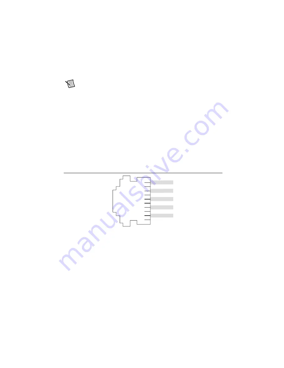
The cDAQ controller has an RS-232 (RJ50) 10-position modular jack, shown in Figure 1-1
or 1-2, to which you can connect devices such as displays or input devices. Use the Serial VIs to
read from and write to the serial port. Refer to the
LabVIEW Help
for information about the
Serial VIs. Refer to Figure 1-27 for pin locations and signal descriptions.
Figure 1-27.
RS-232 Serial Port Pin Locations
You can use the Ring Indicator (RI) on pin 2 to wake the controller from a low power state. You
can drive RI with logic-level signals where a high level greater than 2.4 V signals a wake event.
Power Connector
Refer to the
Wiring Power to the cDAQ Controller
section and the specifications document for
your cDAQ controller for more information about the power connector.
SD Card Removable Storage
The cDAQ controller features an SD card slot that can read from and write to NI-approved SD
cards. Go to
ni.com/info
and enter Info Code
exyerk
for information about best practices
for data logging performance with cDAQ controllers.
3
CT
S
4 RT
S
5 D
S
R
6 GND
7 DTR
8
TXD
9 RXD
10 DCD
1 No Connect
2 RI


