Getting Started with AKD EtherCAT Drives and NI SoftMotion
|
© National Instruments
|
13
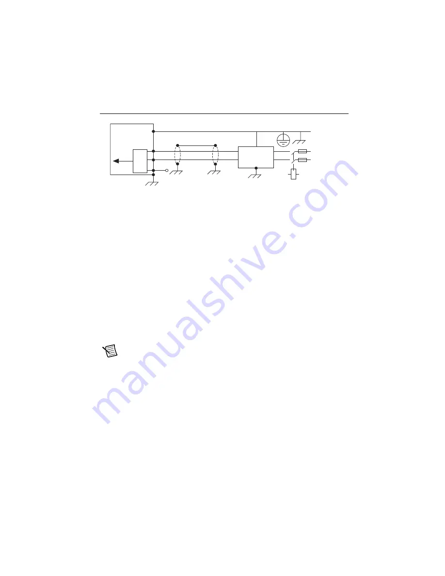
Figure 12 shows single-phase connection.
Figure 12.
AC Input Power Single-Phase Connection
Confirm Drive Connections
After all hardware connections have been made complete the following steps to confirm the
AKD hardware setup.
1.
Power on the RT controller.
2.
Apply AC power to the AKD drive.
3.
Turn on the +24 V power supply. After logic power is supplied to the drive, the drive
displays the following sequence of flashes in the LED indicators.
a.
- -
b.
[]
c.
Drive IP address, flashed sequentially
d.
Drive status, either the operation mode or the fault or warning code if there is a fault
or warning condition. The operation modes are as follows:
•
o0—torque mode (current mode)
•
o1—velocity mode
•
o2—position mode
Note
If the drive shows a fault or warning code, refer to the
AKD Fault and
Warning Messages Card
that came with the drive or the
NI SoftMotion Module Help
for more information about the fault or warning, including possible solutions. You
can use the
Interactive Test Panel
dialog box or the Clear Faults method to clear the
drive faults. AKD drive warnings are only displayed on the drive LED indicators and
are not available through NI SoftMotion.
L1
U
s
er-Provided
Filter
(option
a
l)
L2
L
3
L1
Ne
u
tr
a
l (L2)
Protective
E
a
rth
Protective
E
a
rth
DC
O
u
t
AKD
S
ervo Drive


