background image

Getting Started with NI 9512 and P7000 Drives 

|

© National Instruments

|

15

Dynamic Smoothing

Dynamic smoothing is a temporal filter (second-order, low-pass) applied to the command 
sequence to reduce jerk. It helps reduce overshoot and lessens the excitation of mechanical 
resonance in the system. It filters from slightly below the resonant frequency up to well above 
resonance to remove spectral content that would be misrepresented in the motor output and may 
also excite other parts of the machine.

Dynamic smoothing is a very powerful feature for achieving maximum torque from the motor. 
However, it is difficult to optimize and is not necessary for the vast majority of applications. 
Therefore, National Instruments recommends setting both DIP switches to OFF for minimal 
smoothing.

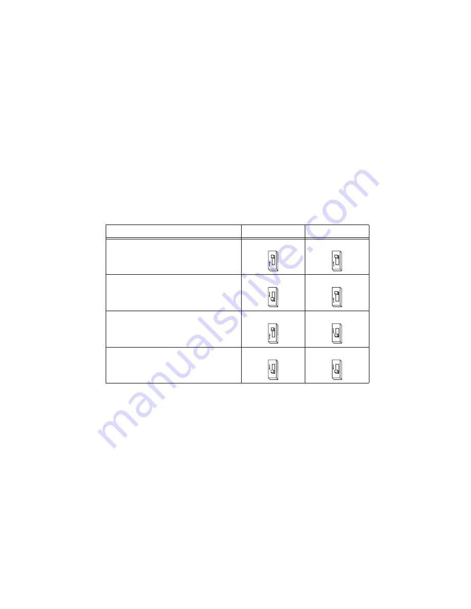
Table 8 lists the dynamic smoothing switch settings.

Table 8.  

Dynamic Smoothing DIP Switch Settings

Dynamic Smoothing

S2–8

S2–9

Minimal

OFF

OFF

Moderate

ON

OFF

Heavy

OFF

ON

Aggressive

ON

ON

8

O

F
F

9

O

F
F

8

O
N

9

O

F
F

8

O

F
F

9

O
N

8

O
N

9

O
N

Содержание 9512 C Series

Страница 1: ...the Drive 6 Step 3 Configure the DIP Switches 8 Step 4 Connect the NI 9512 to the P7000 Drive 17 Step 5 Connect Power to the P7000 Drive 19 Step 6 Configure the P7000 Drive with the Serial Port Optional 21 Software Configuration and Installation 23 Step 1 Install the P7000 Tools Optional 23 Step 2 Test the Motor With the P7000 Tools Optional 27 Step 3 Install Software on and Configure the NI RT Co...

Страница 2: ...9512 C Series drive interface module NI 9512 to P7000 stepper drives connectivity bundle This product contains the following items A cable to directly connect the NI 9512 DSUB with the P7000 series stepper drive A 37 pin terminal block and cable for connecting the NI 9512 MDR connector to other I O NI real time controller CompactRIO controller and chassis that support the RIO Scan Interface Tip To...

Страница 3: ...with the product and are available at ni com manuals Operating instructions for the controller and NI 9512 C Series module P70360 AC High Performance Micro stepping Drive Reference Guide Use this document to learn additional information about the electrical and mechanical aspects of the P70360 AC stepper drive including important safety information P70530 DC High Performance Micro stepping Drive R...

Страница 4: ... methods events dialog boxes and so on The LabVIEW Help also lists the LabVIEW documentation resources available from National Instruments Access the LabVIEW Help by selecting Help LabVIEW Help Getting Started with LabVIEW Use this document as a tutorial to familiarize yourself with the LabVIEW graphical programming environment and the basic LabVIEW features you use to build data acquisition and i...

Страница 5: ... serial number after you install the controller a Make sure that no power is connected to the controller or the chassis b Align the controller with the chassis as shown in Figure 2 Figure 2 Installing the Controller on the Chassis Eight Slot Chassis Shown c Slide the controller onto the controller slot on the chassis Press firmly to ensure the chassis connector and the controller connector are mat...

Страница 6: ... 4 of the chassis Step 2 Connect the Stepper Motor to the Drive Connect the stepper motor as shown in Figure 3 The NI stepper motors are highly recommended as they are optimized to work with the P7000 series stepper drives Caution Do not hot plug the motor connector Also avoid whiskers from stranded phase leads protruding from the motor plug Figure 3 Connecting the Stepper Motor The NI stepper mot...

Страница 7: ... motors that provide optimum performance when matched with the P7000 drive The motors have a four flying lead configuration If your motor has six or eight leads refer to Figures 4 and 5 for connection options Figure 4 Six Lead Connection Options Phase A Phase A Phase B Phase B NC NC NC Not Connected Phase A Phase A Phase B Phase B NC NC 6 Wire Half Coil Connection Higher Speed Lower Torque 6 Wire ...

Страница 8: ...S2 12 in the OFF position for the P70360 drive Figure 6 DIP Switches in OFF Position for P70360 Drive Phase B Phase A Phase A Phase B 8 Wire Parallel Connection Higher Speed Lower Torque Phase B Phase A Phase A Phase B 8 Wire Series Connection Higher Torque Lower Speed Phase B Phase A Phase A Phase B NC NC NC NC 8 Wire Half Coil Connection Higher Speed Lower Torque NC Not Connected 0 1 2 3 4 5 6 7...

Страница 9: ...ettings that correspond to the switch settings Note For DIP switch settings to take effect you must power cycle the P7000 series stepper drive whenever you make changes Table 2 DIP Switch Positions Motor Selection Step Resolution S1 S2 1 S2 2 S2 3 S2 4 Motor Dependent Motor Dependent ON OFF ON Load Inertia Dynamic Smoothing Current Reduction Multi stepping Encoderless Stall Detection S2 5 S2 6 S2 ...

Страница 10: ...sitions Load inertia 0 1 refer to Table 7 for switch positions Dynamic smoothing Minimal refer to Table 8 for switch positions Current reduction Enabled refer to Table 9 for switch positions Multistepping Disabled refer to Table 10 for switch positions Encoderless stall detection Disabled refer to Table 11 for switch positions Table 4 P70360 Compatible Motor DIP Switch Settings Motor Frame Motor S...

Страница 11: ... Motor S1 S2 1 NI NEMA 17 CTP 10 ELF 10 D ON CTP 11 ELF 11 E ON CTP 12 ELF 10 F ON Table 4 P70360 Compatible Motor DIP Switch Settings Continued Motor Frame Motor S1 S2 1 0 1 2 3 4 5 6 7 8 9 A B C D E F 1 O F F 0 1 2 3 4 5 6 7 8 9 A B C D E F 1 O F F 0 1 2 3 4 5 6 7 8 9 A B C D E F 1 O F F 0 1 2 3 4 5 6 7 8 9 A B C D E F 1 O F F 0 1 2 3 4 5 6 7 8 9 A B C D E F 1 O N 0 1 2 3 4 5 6 7 8 9 A B C D E F...

Страница 12: ...ion using P7000 Tools 0 OFF Table 5 P70530 Compatible Motor DIP Switch Settings Continued Motor Frame Motor S1 S2 1 0 1 2 3 4 5 6 7 8 9 A B C D E F 1 O F F 0 1 2 3 4 5 6 7 8 9 A B C D E F 1 O F F 0 1 2 3 4 5 6 7 8 9 A B C D E F 1 O F F 0 1 2 3 4 5 6 7 8 9 A B C D E F 1 O N 0 1 2 3 4 5 6 7 8 9 A B C D E F 1 O N 0 1 2 3 4 5 6 7 8 9 A B C D E F 1 O N 0 1 2 3 4 5 6 7 8 9 A B C D E F 1 O F F ...

Страница 13: ... rotor inertia ratio These switches select the gain parameter the drive uses to stabilize the motor You can calculate the load inertia by hand or by using the Motioneering Table 6 Step Resolution DIP Switch Settings Resolution S2 2 S2 3 S2 4 200 Full Step ON ON ON 400 Half Step OFF ON ON 5 000 ON OFF ON 10 000 OFF OFF ON 18 000 ON ON OFF 25 000 OFF OFF OFF 25 400 OFF ON OFF 50 000 ON OFF OFF 2 O N...

Страница 14: ...witch settings Table 7 Load Inertia DIP Switch Settings Load to Rotor Inertia Ratio S2 5 S2 6 S2 7 0 1 OFF OFF OFF 1 1 5 ON OFF OFF 1 5 2 5 OFF ON OFF 2 5 5 0 ON ON OFF 5 0 7 0 OFF OFF ON 7 0 12 0 ON OFF ON 12 0 20 0 OFF ON ON 20 0 32 0 ON ON ON 5 O F F 6 O F F 7 O F F 5 O N 6 O F F 7 O F F 5 O F F 6 O N 7 O F F 5 O N 6 O N 7 O F F 5 O F F 6 O F F 7 O N 5 O N 6 O F F 7 O N 5 O F F 6 O N 7 O N 5 O ...

Страница 15: ...e misrepresented in the motor output and may also excite other parts of the machine Dynamic smoothing is a very powerful feature for achieving maximum torque from the motor However it is difficult to optimize and is not necessary for the vast majority of applications Therefore National Instruments recommends setting both DIP switches to OFF for minimal smoothing Table 8 lists the dynamic smoothing...

Страница 16: ...settings Note Current reduction is enabled when switch S2 10 is OFF Multistepping Multistepping is similar to dynamic smoothing except it is a much more aggressive use of the filter Typically it results in a filter that begins to roll off two octaves below the resonant frequency This is intended for use with coarse resolution full half step input pulses to smooth large steps into a continuous trai...

Страница 17: ...y of this feature when using third party motors Step 4 Connect the NI 9512 to the P7000 Drive Use the direct connect cable to connect the NI 9512 to the P7000 drive 1 Connect the NI 9512 module DSUB connector to the P7000 series drive Command I O connector using the NI 9512 to P7000 cable 2 Connect the power supply to the NI 9512 to P7000 direct connect cable Vsup inputs Note Refer to the Specific...

Страница 18: ...ies Drive Connection Diagram 1 C Series Chassis 2 NI 9512 MDR Connector 3 NI 9512 DSUB Connector 4 NI 9512 Module 5 Stepper Motor 6 NI 9512 to P7000 Direct Connect Cable 7 P7000 Series Stepper Drive 8 P7000 Command I O Connector 9 NI 951x MDR to Terminal Block Cable 10 37 pin Terminal Block 11 Power Supply Vsup 2 3 4 9 6 1 7 10 11 5 8 ...

Страница 19: ...r pin descriptions If you are using the P70530 drive connect DC power as shown in Figure 11 Refer to Table 13 for DC power connector pin descriptions Connecting AC Power to the P70360 Caution Do not use J7 as an on off switch Hot plugging damages the connector Table 12 J7 AC Power for 320 VDC Bus Pin Description J7 1 120 230 VAC line J7 2 230 VAC neutral 37 36 35 34 33 32 31 30 29 28 27 26 25 24 2...

Страница 20: ... the LED to flash and the motor to audibly squeal This is expected operation as the drive is measuring the motor windings to optimize its settings Once complete the status LED should illuminate green If it is not refer to the Tips and Troubleshooting section Figure 11 DC Power Connector J7 3 120 VAC neutral J7 4 PE Protective Earth Table 12 J7 AC Power for 320 VDC Bus Continued Pin Description J7 ...

Страница 21: ... Configure the NI RT Controller in the Software Configuration and Installation section to configure the RT target 1 Connect the RS 232 serial communication cable between the drive and an available COM port on the computer You must set the COM port to the following settings Baud Rate 19 200 Data Bits 8 Parity Even Stop Bits 1 Flow Control None Table 13 J7 DC Power Pin Description J7 1 Bus Plus powe...

Страница 22: ...0 Drives 2 Configure a COM port to be used with the serial cable To change your COM port open the Device Manager click Ports COM LPT and double click the desired COM port as shown in Figure 12 Figure 12 Selecting the COM1 Port in the Device Manager ...

Страница 23: ...p Figure 13 COM Port Settings Software Configuration and Installation Step 1 Install the P7000 Tools Optional 1 Install the P7000 Tools configuration software You can find the software at ni com updates Note If you have a previous version of P7000 Tools on your system the installation wizard automatically uninstalls it After the previous version is uninstalled you must run the installer again to i...

Страница 24: ...24 ni com Getting Started with NI 9512 and P7000 Drives 2 Launch the P7000 Tools configuration software The setup wizard appears as shown in Figure 14 Figure 14 P7000 Setup Wizard ...

Страница 25: ... shown in Figure 15 You may enter a new name for the drive or leave the default Figure 15 Product Selection 4 Click Next 5 In the motor selection dialog shown in Figure 16 select the NI stepper motor you have connected to the drive If you are using a third party motor select None from the list click the Motor File Editor button and enter the motor information The T23NRLC motor is selected in this ...

Страница 26: ...e required for these settings 8 Click Finish Your drive setup is complete The P7000 Tools configuration software downloads the new configuration data to your drive and performs an initialization process with the motor You may see a dialog box such as the one in shown Figure 17 when the configuration data is about to download Click Yes to continue the download process Figure 17 Motor Type Conflict ...

Страница 27: ...he negative and positive directions using the following arrows on the Motion Toolbar Note After testing the configuration settings the RS 232 serial communication cable between the computer and P7000 series stepper drive is no longer needed but you can leave it connected Table 14 Motion Toolbar Buttons Icon Behavior Description Jog motor negative Jogs the motor in the negative direction at the sel...

Страница 28: ...eneral Settings section matches the serial number on the device 5 If you do not want to format the disk on the controller eliminating all installed software and files skip to step 15 6 Set the Safe Mode switch on the controller to the On position 7 Power on the controller If it is already powered on press the Reset button on the controller to reboot it 8 Right click the controller under Remote Sys...

Страница 29: ...ke most C Series modules NI 951x modules are not directly configurable from the Project Explorer window and no I O variables are directly available under the module Tip Refer to the Select Programming Mode Dialog Box topic of the CompactRIO Reference and Procedures Scan Interface help file for more information about Scan Interface mode Use a LabVIEW project to manage VIs targets and I O modules on...

Страница 30: ... Time CompactRIO 4 Select the CompactRIO controller to add to the project and click OK 5 If you have LabVIEW FPGA installed the Select Programming Mode dialog box appears Select Scan Interface to put the system into Scan Interface mode Tip Use the CompactRIO Chassis Properties dialog box to change the programming mode in an existing project Right click the CompactRIO chassis in the Project Explore...

Страница 31: ... Series module Step 6 Configure the NI 9512 Axis In this section you will configure the axis associated with the NI 9512 C Series module for use with the P7000 series stepper drive using the Axis Configuration dialog box The Axis Configuration dialog box includes configuration options for stepper drive command signals feedback devices motion and digital I O trajectory and axis setup Figure 20 show...

Страница 32: ... page confirm that Loop Mode is set to Open Loop Axes configured in open loop mode produce step outputs but do not require feedback from the motor to verify position 3 Also on the General Settings page confirm that the Axis Enabled and Enable Drive on Transition to Active Mode checkboxes contain checkmarks These selections configure the axes to automatically activate when the NI Scan Engine switch...

Страница 33: ...and clear the Enable checkbox 7 Click the Digital I O button to open the Digital I O page and map DI 1 DSUB Pin 8 to Drive Fault Alarm a Double click the text in the Mapping column and select Drive Fault Alarm from the dropdown list b Ensure that the DI 1 settings match the following Input Type Sourcing Active State Off Digital Filter 50 µs 8 Configure any additional I O settings according to your...

Страница 34: ...microstepping resolution Table 6 shows the step resolution switch settings 2 Right click the axis in the Project Explorer window and select Interactive Test Panel from the shortcut menu Opening this dialog box sends the axis settings to the hardware and activates the I O on the module Tip Click the Help button on the bottom of the dialog box for detailed information about the items available in th...

Страница 35: ...on is disabled Enable current reduction Refer to the Current Reduction section in the Hardware Installation and Configuration section for instructions on enabling The Motor Moves Backwards To reverse the motor rotation direction do one of the following Switch A with A Switch B with B Switch A A with B B Refer to Step 2 Connect the Stepper Motor to the Drive in the Hardware Installation and Configu...

Страница 36: ... resources to email and phone assistance from NI Application Engineers Visit ni com services for NI Factory Installation Services repairs extended warranty calibration and other services Visit ni com register to register your National Instruments product Product registration facilitates technical support and ensures that you receive important information updates from NI A Declaration of Conformity...

Отзывы: