Chapter 3
Theory of Operation
© National Instruments Corporation
3-7
SCXI-1100 User Manual
chassis), and then releasing INTR* high. At this point, the SS* of the desired slot is asserted low
and the data acquisition board can communicate with the module in that slot according to the SPI
protocol.
Digital Interface Circuitry
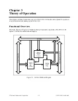
Figure 3-4 shows a diagram of the SCXI-1100 and SCXIbus digital interface circuitry.
Digital
Interface
SCXIbus
Buffered Serial
Data
Buffered Digital
Control Signals
SERDATIN
DAQD*/A
SLOT0SEL*
SERCLK
SERDATOUT
Rear
Signal Connector
MISO
SPICLK
INTR*
D*/A
MOSI
SS*
Figure 3-4. Digital Interface Circuitry Block Diagram
The digital interface circuitry is divided into a data acquisition section and an SCXIbus section.
The SCXI-1100 connects to the SCXIbus via a 4x24 metral receptacle and to the data acquisition
board via a 50-pin ribbon-cable header.

