


Getting Started with NI Integrated Steppers and NI 73xx Motion Controllers
|
© National Instruments
|
9
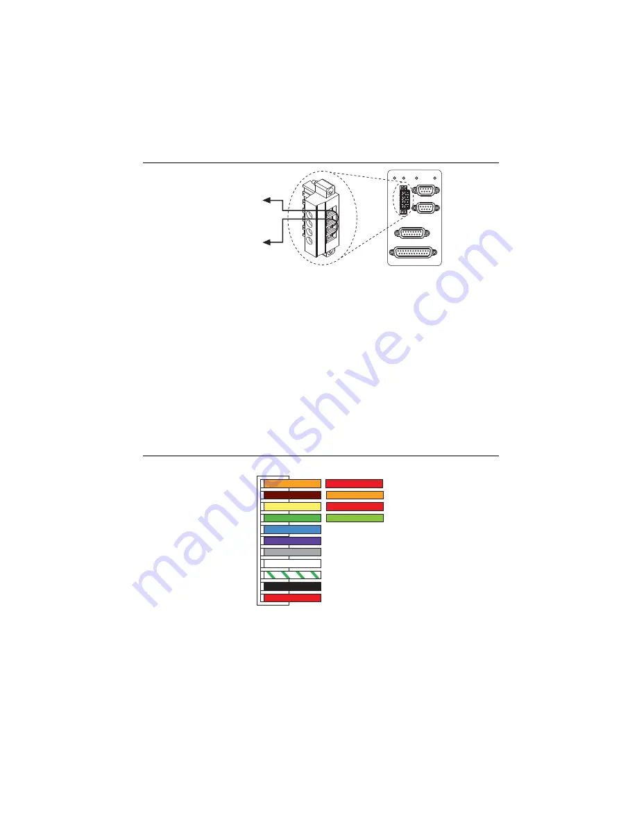
Figure 3 shows the power terminal block.
Figure 3.
UMI-7772/7774 Power Connection
Step 2: Connect the Drive Command Signals to the
UMI-7772/7774
Complete the following steps to connect the Drive Command signals to the UMI-7772/7774.
1.
Connect the DB15M pigtail cable to the UMI-7772/7774 Axis 1 Control connector.
2.
Connect the integrated stepper Step- wire (brown) to the DB15M cable pin 4 wire (orange)
which corresponds to the UMI-7772/7774 Step (CW) terminal.
3.
Connect the integrated stepper Dir- wire (green) to the DB15M cable pin 12 wire (light
green) which corresponds to the UMI-7772/7774 Dir (CCW) terminal.
4.
Connect the integrated stepper Step+ wire (orange) and Dir+ wire (yellow) to the DB15M
cable pin 3 wire (red) which corresponds to the UMI-7772/7774 +5V OUT terminal.
Figure 4 shows the connections.
Figure 4.
NI ISM-7400/7401/7402 to DB15M Ca
b
le Drive Command Connections
C
V
Viso
Ciso
+24 V External
) Terminal
V
(24VDC±10%)
(5-30VDC)
Viso
INHIBIT ALL
POWER
POWER
TRIGGER / BREAKPOINT
DIGITAL I/O
ANALOG INPUT
GLOBAL STOP
INTERLOCK
+24 V External
Supply(–) Terminal
V
Viso
Ciso
C
(1)
S
TEP+
(2)
S
TEP–
(
3
)DIR+
(4)DIR–
(5)EN+
(6)EN–
(7)OUT+
(8)OUT–
(9)N.C.
(10)V–
(11)V+
(4)
S
tep (CW)
(12)Dir (CCW)
(
3
)+5V OUT
(
3
)+5V OUT
NI I
S
M-7400/7401/7402
NI DB15M C
a
ble


