


Confidential Page
6
1/30/2013
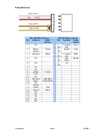
Relay Harness
NFT-4550 Main Harness
NFT-4550 Relay Harness
Pin
Function
Main
Harness
Pin
Function
Relay
Socket
1 NC
1
(30)
To starter
wire
Red
2 Starter
Disable
Orange
2
(85)
Ignition Yelow
3 Not
Used Brown 3
(87a)
To starter
wire
White
4 NC
4
(86)
Neg.
Output
Orange
5 NC
5
(87)
NC
6 NC
7 NC
8 Ignition Yellow
9 NC
10 NC
11
Not Used
Light Green
12 Input
1 Brown/White
13 NC
14
Primary
Power Red
15 Ground
Black
16 NC
17 NC
18 NC
19 NC
20 NC