Nat SM245 Скачать руководство пользователя страница 14

Model 245 Speaker Amplifier Manual  

SM245 Rev. 4.10 


2.3.2  

Cautions 

In all installations, use shielded cable exactly as shown and ground as indicated. 
Significant problems may result from not following these guidelines, especially with 
regard to ground loop noise. 
 

2.3.3  

Cabling and Wiring 

All unshielded wire shall be selected in accordance with AC43.13-1B Change 1, 
Paragraphs 11-76 through 11-78.  Wire types should be to MIL-W-22759 as specified in 
AC43.13-1B Change 1, Paragraphs 11-85, 11-86, and listed in Table 11-11.  For 
shielded wire applications, use Tefzel MIL-C-27500 shielded wire with solder sleeves 
(for shield terminations) to make the most compact and easily terminated interconnect.  
Follow the wiring diagrams in Section 2.6 as required. 


Allow 3 inches from the end of the wire to the shield termination to allow the backshell to 
be easily installed.   
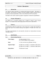
 
2.3.3.2  

Pin Identification 

The following table specifies the functions of the connector pins. 


PIN #  FUNCTION 

+ SIGNAL INPUT 

SIGNAL GROUND 

- SIGNAL INPUT 

- OUTPUT 

+ OUTPUT 

POWER GROUND 

+ 28 VDC IN 


Connection to the unit should be made with twisted pair, shielded cable. The shield 
should be attached to the airframe at one end only. Pins A, B, and C (the input pins) 
should be wired using 22 - 24 AWG wire. The output (pins D and E) and power (pins F 
and G) should be wired using wire no smaller than 20 AWG. 


The finish on the case is electrically conductive, and it is not necessary to remove the 
finish for electrical bonding. 


Caution: do not connect the audio outputs to power return or chassis ground.


2.3.4  

Mechanical Installation 

The Model 245 may be mounted in any position. No shock or vibration isolators are 
required.   


For proper heat dissipation, the Model 245 should be mounted on a metal surface of at 
least 100 square inches. The amplifier case should also be grounded to the airframe. 

Page 2-2 


Jun 

2

3, 2005 

ENG-FORM: 805-0108.DOT 
 

CONFIDENTIAL AND PROPRIETARY TO NORTHERN AIRBORNE TECHNOLOGY LTD.


Содержание SM245

Страница 1: ...Y LTD SM245 245 Speaker Amplifier INSTALLATION AND OPERATION MANUAL REV 4 10 June 23 2005 Northern Airborne Technology Ltd 1925 Kirschner Road Kelowna BC Canada V1Y 4N7 Telephone 250 763 2232 Facsimile 250 762 3374 Copyright 2005 by Northern Airborne Technology ...

Страница 2: ......

Страница 3: ...ONFIDENTIAL AND PROPRIETARY TO NORTHERN AIRBORNE TECHNOLOGY LTD Northern Airborne Technology Ltd has acquired the assets of dB Systems Inc and has revised and reissued this manual in standard NAT format Northern Airborne Technology Ltd will be responsible for all future amendments and revisions ...

Страница 4: ......

Страница 5: ... release manual amendments In order to maintain the most accurate and up to date manual these amendments should be carried out immediately upon receipt and recorded on the following amendment record AMENDMENT RECORD Amendment Number Amendment Date Section s Changed Date Entered Entered By 1 Jul 19 06 2 Insert any Amendment Instruction sheets after this page Performed at factory ...

Страница 6: ......

Страница 7: ...e manual Amendment Instructions 1 Remove Pages Replace With Pages 2 3 to 2 4 Rev 4 10 2 3 to 2 4 Rev 4 10 Amendment 1 2 Remove Drawings Section 2 Replace or add Drawings Section 2 245 245 922 0 Rev 1 00 245 245 922 0 Rev 1 01 Note Ensure that all drawings are inserted in the order shown on the latest drawing lists 3 Update the Amendment Record sheet at the front of the manual 4 Insert this page in...

Страница 8: ......

Страница 9: ...l Specifications 1 2 1 4 3 Environmental Specifications 1 2 1 5 Unit Nomenclature 1 2 2 Installation 2 1 Introduction 2 1 2 2 Unpacking and Inspection 2 1 2 2 1 Warranty 2 1 2 3 Installation Procedures 2 1 2 3 1 Warnings 2 1 2 3 2 Cautions 2 2 2 3 3 Cabling and Wiring 2 2 2 3 4 Mechanical Installation 2 2 2 3 5 Post Installation Checks 2 3 2 3 6 Log Entries 2 3 2 4 Continued Airworthiness 2 3 2 5 ...

Страница 10: ......

Страница 11: ...t replacement for the Collins model 356F 3 1 3 Features The Model 245 is rated at 18 watts into a 4 ohm load This is a peak rating intended for speech and music The continuous rating of the amplifier is 10 watts into 4 ohms sine wave For proper heat dissipation the unit should be mounted to a metal surface of at least 100 square inches 1 4 Specifications 1 4 1 Electrical Specifications Power Suppl...

Страница 12: ...F2 BA CL XXXXXXZ BZ AAATZ XXC2 XX Tested under environmental conditions and test procedures in accordance with RTCA DO 160C and qualified to the categories listed in the Environmental Qualification Form in Section 2 of this manual TSO Compliance TSO C50c RTCA DO 214 1 5 Unit Nomenclature Any derivatives of the Model 245 base unit are represented as Model 245 xxx where xxx represents the specific d...

Страница 13: ...the warranty will be activated on date of shipment from NAT Note An appropriately rated facility e g Certified Aircraft Repair Station must install this equipment in accordance with applicable regulations NAT Ltd s warranty is not valid unless the equipment is installed by an authorized NAT Dealer Failure to follow any of the installation instructions or installation by a non certified individual ...

Страница 14: ...ntification The following table specifies the functions of the connector pins PIN FUNCTION A SIGNAL INPUT B SIGNAL GROUND C SIGNAL INPUT D OUTPUT E OUTPUT F POWER GROUND G 28 VDC IN Connection to the unit should be made with twisted pair shielded cable The shield should be attached to the airframe at one end only Pins A B and C the input pins should be wired using 22 24 AWG wire The output pins D ...

Страница 15: ... the following a Check pin G for 28 Vdc relative to ground b Check pin F for continuity to ground less than 0 5 Ω power ground c Check inputs and outputs for correct orientation 2 3 5 2 Power On checks Install the Model 245 and power up the aircraft s systems Verify normal operation of all functions 2 3 6 Log Entries Upon satisfactory completion of all performance checks make the required log entr...

Страница 16: ...CONFIDENTIAL AND PROPRIETARY TO NORTHERN AIRBORNE TECHNOLOGY LTD 2 6 Installation Drawings DRAWING REV DESCRIPTION TYPE Interconnect Speaker Amplifier Generic Interconnect 245 521 0 1 00 Speaker Amplifier Environmental Qual Form 245 245 922 0 1 01 Speaker Amplifier Mech Installation Section 2 ends after these Drawings ...

Страница 17: ...Interconnect ...

Страница 18: ......

Страница 19: ......

Страница 20: ......

Страница 21: ......

Страница 22: ......

Страница 23: ...le of driving a 4 ohm cockpit speaker It is intended to be a direct replacement for the Collins model 356F 3 3 3 Operation Specifics The Model 245 Speaker Amplifier has no operator accessible controls During installation or if the unit has been exchanged it may be a requirement to change internal adjustments This should be done ONLY BY FULLY QUALIFIED PERSONNEL End of section 3 Jun 23 2005 Page 3 ...

Страница 24: ......

Отзывы: