narvi.fi
for 2 full-spectrum heaters
IR-IC1 / Narvi IR-IC1 2 x 800W
Infrared control unit
INSTALLATION AND OPERATING INSTRUCTIONS
EN
INSTALLATIONS- UND BETRIEBSANLEITUNG
DE
Страница 1: ...narvi fi for 2 full spectrum heaters IR IC1 Narvi IR IC1 2 x 800W Infrared control unit INSTALLATION AND OPERATING INSTRUCTIONS EN INSTALLATIONS UND BETRIEBSANLEITUNG DE...
Страница 2: ...ded 17 8 Cleaning 17 9 Disposal 17 10 Specifications 18 10 1 Power unit 18 10 2 Control unit 19 Contents 1 Important information about this guide 3 2 Important safety information 4 2 1 Safety instruct...
Страница 3: ...in a worst case scenario may even be fatal The signal words used have the following meanings Further warnings in this guide about this product ATTENTION This signal word warns of damage to property th...
Страница 4: ...d in each section These are marked by the signal words described above Intended use NARVI infrared controls are exclusively suitable for controlling infrared heaters for use in infrared or sauna cabin...
Страница 5: ...om 10 C to 80 C The electrical cable to the infrared heater must have a minimum cross section of 1 5 mm and be temperature resistant up to 150 C When installed in public saunas a control lamp must be...
Страница 6: ...asons do not use the infrared control if you are under the influence of alcohol medications or drugs Before start up ensure that the infrared heater s is are not covered fire hazard It is recommended...
Страница 7: ...4 m Installation accessories for the control unit Installation and operation instructions The IC 1 infrared control is suitable for dimming one or two infrared heaters each with an output of up to 800...
Страница 8: ...8 20 4 Installation 4 1 Installing the control unit We recommend installing the control unit near the infrared heater 1 At the desired position make a circular cutout diameter 25 mm for example with...
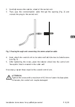
Страница 9: ...he control unit to the cabin wall with the two included screws see Fig 3 5 After tightening the screws place the selector wheel into the control unit base plate that is screwed to the cabin wall Fig 2...
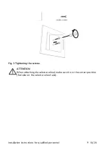
Страница 10: ...dienteil 1 Bedienteil 2 Installation instructions for qualified personnel P 10 20 Fig 3 Tightening the screws ATTENTION When attaching the selector wheel make sure it is in the correct position flat s...
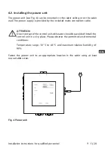
Страница 11: ...hler 1 Installation instructions for qualified personnel P 11 20 EN 4 2 Installing the power unit The power unit see Fig 4 can be mounted on the cabin ceiling or on the cabin wall The power supply is...
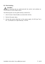
Страница 12: ...ater Connect the plug of the second infrared heater to the IR Emitter 2 socket 4 Connect the data cable of the control unit for the first infrared heater to the Controller 1 socket 5 When using a seco...
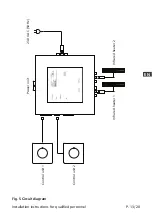
Страница 13: ...800 Watt gesamt 1 5 kW Regelbereich 40 100 Anschlussplan Installation instructions for qualified personnel P 13 20 EN Control unit 1 Power unit 230 V AC 50 Hz Control unit 2 Infrared heater 1 Infrared...
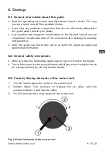
Страница 14: ...cted correctly 2 Remove the power plug 3 Connect the power plug back to the power supply the LED see Fig 6 Pos 3 will light up for approximately 1 second The following tests must be performed by an el...
Страница 15: ...control unit can compromise the safe operation of the unit and result in voiding the warranty and guarantee Store this guide near the control unit to consult it for important safety and operational in...
Страница 16: ...trol unit Fig 6 Pos 1 The power of the infrared heater can be adjusted in a range from 40 to 100 in 10 increments To switch off the infrared heater press the control unit again The heater also switche...
Страница 17: ...Clean the front of the control or power units with a soft cloth and warm water as necessary Do not use steam cleaners high pressure cleaners or sprayed water for cleaning The packaging materials must...
Страница 18: ...l unit 15 m Dimensions W x H x D 152 x 152 x 38 mm Voltage 230 V AC 50 Hz Max infrared heater output 1 5 kW Adjustment ranges Power 40 to 100 in 10 steps Max operating time 30 min Safety devices Autom...
Страница 19: ...P 19 20 EN 10 2 Control unit Environmental conditions Storage temperature 25 C 70 C Operating temperature 10 C 80 C Humidity max 90 Dimensions W x H x D 80 x 80 x 45 mm Installation cutout diameter 2...
Страница 20: ...Narvi Oy Yritt j ntie 1 27230 Lappi Finland Phone 358 20 7416 740 export narvi fi...
Страница 21: ...INSTALLATIONS UND BETRIEBSANLEITUNG DE IR IC1 Narvi IR IC1 2 x 800W Infrarotsteuerung f r 2 Vollspektrumstrahler narvi fi...
Страница 22: ...diese Anleitung vor der Montage und Inbetriebnahme aufmerksam durch Bewahren Sie die Anleitung anschlie end in der N he Ihrer Infrarot bzw Saunakabine auf um jederzeit wichtige Informationen nachlese...
Страница 23: ...rf nur durch eine Elektrofachkraft oder eine ver gleichsweise qualifizierte Person ausgef hrt werden Arbeiten an der Infrarotsteuerung d rfen nur im spannungsfreien Zustand durchgef hrt werden Bei der...
Страница 24: ...wird Personen bei denen das Risiko einer berhitzung besteht z B Herz Kreislauf Erkrankungen sollten im Zweifelsfall vor der Be n tzung einer Infrarot oder Saunakabine einen Arzt befragen Falls ein an...
Страница 25: ...F hren Sie anschlie end die Kommunikationsleitung durch die ffnung Abb 2 und verbinden Sie den Stecker mit dem Bedienteil Abb 2 Durchf hren und Verbinden der Kommunikationsleitung 4 Befestigen Sie ans...
Страница 26: ...Funktionsanzeige am Drehregler Automatische Abschaltung nach 30 mi Neustart durch erneutes dr cken Optionaler Raumtemperatur Sensor Automatisches Erkennen des Sensors Artikelnummer ic 1 Leistung 2 x 8...
Страница 27: ...n Sie die Datenleitung des Beidienteils f r den zweiten Infrarotsrahler mit der Buchse Controller 2 6 Stecken Sie abschlie end den Netzstecker an eine geeignete Steckdose WARNUNG Vergewissern Sie sich...
Страница 28: ...tellungen die in dieser Anleitung nicht ausf hrlich behandelt werden an Ihren H ndler nderungen oder Modifikationen an der Infrarotsteuerung k nnen den sicheren Betrieb gef hrden und f hren zum Erl sc...
Страница 29: ...en 10 Schritte Der Infrarotstrahler wir durch erneutes Dr cken auf das Bedienteil oder nach Ablauf der maximalen Laufzeit von 30min ausgeschaltet 7 Probleml sungen 7 1 Laufzeit berschreitung Nach erre...
Страница 30: ...70 C Betriebstemperatur 10 C bis 40 C Luftfeuchtigkeit max 90 maximale Leitungsl ngen Kommunikationsleitung Leistungsteil Bedienteil 15 m Abmessungen B x H x T 152 x 152 x 38 mm Spannung 230 V AC 50 H...
Страница 31: ...Narvi Oy Yritt j ntie 1 27230 Lappi Finland tel 358 20 7416 740 export narvi fi...