


!
WARNING
•
Risk of fi re!
•
Never obstruct the front opening of the appliance.
•
Do not strike, slam or scratch glass. Do not operate appliance with glass removed, cracked, broken or
scratched.
EN
W415-1673 / A / 10.07.19
25
fi nishing
3
4
4.0 fi nishing
A.
Secure the housing panels as illustrated.
- Secure the top housing panel using 6 screws (Type 5).
(Step 1)
- Secure the bottom housing panel using 5 screws (Type 5).
(Step 2)
- Secure each of the side housing panels using 8 screws per side (Type 2).
(Steps 3 & 4)
- Secure each standoff to the bottom housing panel using 2 screws per side (Type 2).
(Steps 5 & 6)
1
2
NOTE :
DO NOT PINCH WIRES.
5
6
TYPE 5 (X11)
TYPE 2 (X20)
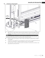
4.1
housing panel installation
When using optional fi nishing accessories, the framing dimensions and fi nishing materials may differ from
what is outlined in the section below; refer to the leafl et instructions supplied in the accessory kit for specifi c
framing and fi nishing specifi cations.
note:
If installing the remote receiver into the side of the appliance, see “receiver / location wiring” section.
note:


