


5
LEFT
BURNER
SIDE
BURNER
CENTER
BURNER
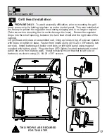
LIGHTING INSTRUCTIONS
RIGHT
BURNER
The propane cylinder is equipped with an excess flow device. Unless all burners are turned off prior to
turning the cylinder on, only small flames will be achievable.
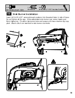
SIDE BURNER LIGHTING
1. OPEN SIDE BURNER
COVER.
4. IF THE BURNER WILL NOT IGNITE
WITHIN 5 SECONDS, TURN THE
CONTROL KNOB TO THE ‘OFF’
POSITION AND WAIT 5 MINUTES
FOR ANY EXCESS GAS TO
DISSIPATE. EITHER REPEAT STEPS
2 AND 3 OR LIGHT WITH A MATCH.
3. IF THE BURNER DOES NOT
IGNITE, THEN IMMEDIATELY
TURN THE CONTROL KNOB
BACK TO THE ‘OFF’ POSITION
AND REPEAT STEP 2 SEVERAL
TIMES.
2. PUSH AND TURN THE
SIDE BURNER CONTROL
KNOB SLOWLY TO THE
‘HI’ POSITION. THIS
ACTION WILL IGNITE
THE SIDE BURNER
OPEN LID.
ENSURING BURNER CONTROLS
ARE IN THE OFF POSITION, TURN
ON THE GAS SUPPLY VALVE.
MAIN BURNER LIGHTING
1. PUSH AND TURN ANY MAIN
BURNER KNOB SLOWLY TO
THE ’HI’ POSTION. THIS ACTION
WILL IGNITE THE PILOT FLAME
WHICH WILL IN TURN LIGHT THE
SELECTED BURNER. IF THE
PILOT LIGHTS, CONTINUE TO
PUSH DOWN ON THE CONTROL
KNOB UNTIL THE BURNER
LIGHTS AND THEN RELEASE.
2. IF THE PILOT DOES NOT
IGNITE, THEN IMMEDIATELY
TURN THE CONTROL KNOB
BACK TO THE ‘OFF POSITION
AND REPEAT STEP 1 SEVERAL
TIMES.
3. IF THE PILOT AND BURNER WILL
NOT IGNITE WITHIN 5 SECONDS,
TURN THE CONTROL KNOB TO THE
‘OFF’ POSITION AND WAIT 5
MINUTES FOR ANY EXCESS GAS TO
DISSIPATE. EITHER REPEAT STEPS 1
AND 2 OR LIGHT WITH A MATCH.
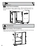
REAR BURNER LIGHTING
(ROTISSERIE BURNER)
Do not use the rear burner (rotisserie burner) with the main burners operating.
1. REMOVE THE
WARMING RACK
2. PUSH AND TURN THE
ROTISSERIE BURNER CONTROL
KNOB SLOWLY TO THE ‘HI’
POSITION. THIS ACTION WILL
IGNITE THE PILOT FLAME WHICH
WILL IN TURN LIGHT THE
BURNER. IF THE PILOT LIGHTS,
CONTINUE TO PUSH DOWN ON
THE BURNER CONTROL KNOB
UNTIL THE BURNER LIGHTS
THEN RELEASE.
3. IF THE BURNER DOES NOT
IGNITE, THEN IMMEDIATELY
TURN THE CONTROL KNOB
BACK TO THE ‘OFF’ POSITION
AND REPEAT STEP 2 SEVERAL
TIMES.
FOR ANY EXCESS GAS TO
DISSIPATE. EITHER REPEAT STEPS
2 AND 3 OR LIGHT WITH A MATCH.
INFRARED
BURNER
REAR
BURNER
If lighting the unit with a match, clip the match into the supplied lighting rod. Hold the lit match down
through the grill and sear plate while turning the corresponding burner valve to high.
4. IF THE BURNER WILL NOT IGNITE WITHIN 5
SECONDS, TURN THE CONTROL KNOB TO
THE ‘OFF’ POSITION AND WAIT 5 MINUTES
Содержание MIRAGE 605
Страница 33: ...33 3 3...
Страница 34: ...34 NOTES...
Страница 36: ...36...
Страница 70: ...34 3 3...
Страница 71: ...NOTES 35...
Страница 72: ...36...


