Page 5
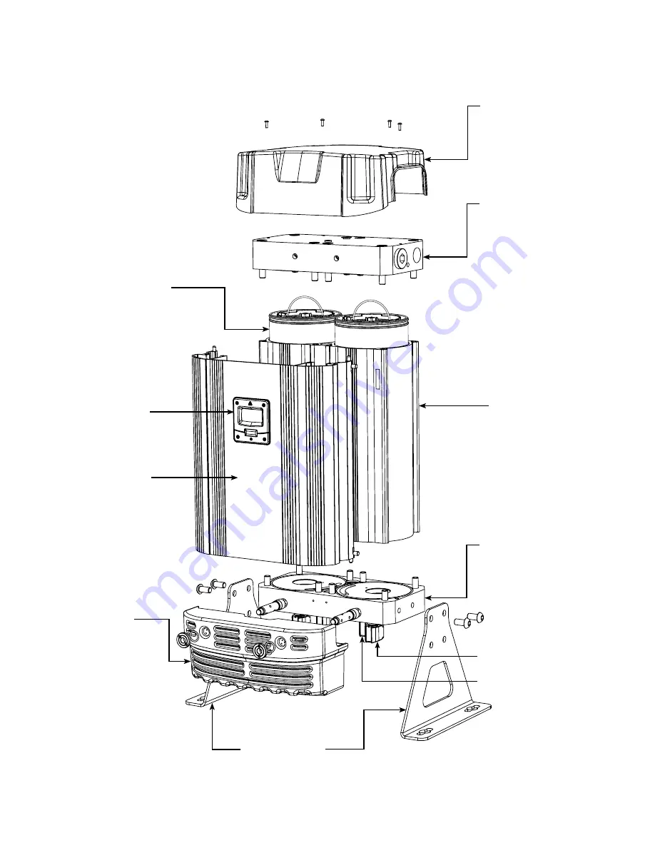
2. PRODUCT ASSEMBLY
TOP COVER
INLET/OUTLET
(TOP) MANIFOLD
ASSEMBLY
DESICCANT
CARTRIDGES
DRYER
CONTROLLER
SHROUD
COLUMN
BOTTOM
MANIFOLD
DRYER LEGS
SILENCER
BOX
MODELS NDL-060 TO NDL-090
EXHAUST VALVE
INLET VALVE
Страница 1: ...D Series1 HEATLESS COMPRESSED AIR DRYER MAINTENANCE SERVICE MANUAL www n psi com NDL 060 NDL 070 NDL 080 NDL 090 NDL 100 NDL 110 NDL 120 NDL 130...
Страница 2: ...s outlined in this document contact nano purification solutions before proceeding Read this document carefully before attempting to service the dryer General Safety For your own safety when carrying o...
Страница 3: ...Control Exhaust Valve Replacement NDL 060 NDL 090 6 1 Service B Instructions Inlet Valve Replacement NDL 100 NDL 130 6 2 Service B Instructions Inlet Control Exhaust Valves Replacement NDL 100 TO NDL...
Страница 4: ...s 3 Years 4 Years 5 Years 6 Years 7 Years 8 Years 9 Years 11 Years 10 Years 12 Years 2 Years 12 000 Hrs 4 Years 24 000 Hrs 6 Years 36 000 Hrs 8 Years 48 000 Hrs 10 Years 60 000 Hrs NDL 070 NDL 060 NDL...
Страница 5: ...SSEMBLY TOP COVER INLET OUTLET TOP MANIFOLD ASSEMBLY DESICCANT CARTRIDGES DRYER CONTROLLER DRYER SHROUD DRYER COLUMN BOTTOM MANIFOLD ASSEMBLY DRYER LEGS SILENCER BOX MODELS NDL 060 TO NDL 090 EXHAUST...
Страница 6: ...LY MODELS NDL 100 TO NDL 130 TOP COVER OUTLET TOP MANIFOLD ASSEMBLY DESICCANT CARTRIDGES DRYER CONTROLLER DRYER COLUMN INLET BOTTOM MANIFOLD ASSEMBLY DRYER LEGS SILENCER BOX DRYER SHROUD EXHAUST VALVE...
Страница 7: ...is isolated from the compressed air supply and fully depressurised Also ensure the product is switched off and or isolated from the mains power PROCEDURES Close the inlet and outlet valves The dryer m...
Страница 8: ...s below the top surface of the dryer column 9 Insert the new gasket seal placing it into the gasket groove in the top manifold ensuring it is fully retained 10 Ensure both handles are folded flat 11 R...
Страница 9: ...ES 1 Lift handle and remove the upper cartridges from the dryer and discard them NOTE Ensure the upper cartridges have disconnected from the cartridge joining rings and the lower cartridges before att...
Страница 10: ...gs from the solenoids by removing the 4x plug screws and releasing the plugs See Figure 1 SOLENOID PLUG PLUG SCREW 3 Remove the solenoid coils by unclipping and sliding the coils from the valve stems...
Страница 11: ...ttom manifold See Figure 4 5 Remove and discard the 4x diaphragms from the bottom manifold See Figure 4 6 Replace the 4x diaphragms and 4x exhaust valves from the service kit and replace the 16x M5 so...
Страница 12: ...ottom manifold and from each other See Figure 2 INLET BLOCK 1 Ensure the dryer is shut down and fully depressurised before attempting any maintenance work See page 7 Figure 1 6x M8 HEAD CAP SCREWS 2 R...
Страница 13: ...See Figure 3 6 Discard the old inlet valves Figure 5 SPILL PORT VALVE RIDGE DETAILS 8 Replace the 6x M8 socket head cap screws and 6x washers and tighten at a torque setting of 20Nm See Figure 2 6 1 S...
Страница 14: ...S 1 Remove the 6x fixing screws and 6x washers to release the inlet control valves from the valve block See Figure 1 2 Discard the valve gaskets and inlet control valves and replace from the service p...
Страница 15: ...ng nut using a 20mm pin spanner and remove the O ring to release the silencer box from the assembly See Figure 1 3 Remove the 8x M5 socket head screws and the 8x spring washers and remove the exhaust...
Страница 16: ...column 4 Using a pair of circlip pliers remove each circlip 5 Remove the valve seat using a pair of bearing pullers and then remove the valve 6 Remove the DU bush and replace it from the service kit 7...
Страница 17: ...re 1 4 Remove the screw from the sensor plug and detach it from the dew point sensor assembly See Figure 3 4 SENSOR PLUG SCREW SENSOR PLUG CONTROLLER CHASSIS PLATE 1 Ensure the dryer is shutdown and f...
Страница 18: ...assis plate using the 2x fixing screws 8 Replace the sensor plug and screw to complete the sensor assembly See Figure 3 4 9 Close the shroud and ensure the latches are in position 10 Replace the top c...
Страница 19: ...he dryer is on and running see dryer start up procedure on page 18 2 Place a magnet over the controller reset area shown in Figure 1 for 8 10 seconds until the dryer re sets See Figure 1 3 Once re set...
Страница 20: ...Page 20 9 MANIFOLD TIGHTENING SEQUENCES 1 2 3 4 5 6 7 8 1 2 3 4 5 6 7 8 Top manifold Bottom manifold FOR MODELS NDL 060 TO NDL 130...
Страница 21: ...work Ensure the inlet operating pressure parameters are between 4 16 barg Ensure the inlet air temperature is between 1 5 C 50 C Open the inlet and outlet valves Turn on electrical power to the dryer...
Страница 22: ...icable If the dew point is not achieved the dewpoint reading on the display will alternate with dewpoint alarm every 5 seconds The no volt alarm will also activate Contact the service department and r...
Страница 23: ...ctly if there is power to the coil replace valve A correctly working valve outputs an audible click when it energises 12 Check inlet air supply Failure of dryer to cycle 13 Failure to initialise dryer...
Страница 24: ...he following table allows the customer to document the service history of the product and to make notes related to each service DRYER SERVICE RECORD PRODUCT CODE PRODUCT SERIAL NO SERVICE TYPE A B C D...
Страница 25: ...Page 25 NOTES...
Страница 26: ...Page 26 11330 Vanstory Blvd Huntersville NC 28078 Telephone 704 897 2182 Internet www n psi com E mail support n psi com...