69
Test Mode
7. Troubleshooting
Troubleshooting
Disassembling/Replacement Procedure
- Must be performed by a technician -
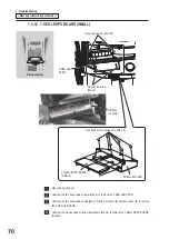
7-3-11 JACKPOT SLOPE/SLOPE SENSOR (Receiver/Transmitter)
Field assembly
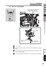
Unscrew the pan
head screw
(w/washers) (M5 x 12).
BALLSLOPE UNIT
BALLSLOPE UNIT
Unscrew the three pan head screws
(w/washers) (M5 x 12).
Unscrew the pan
head screw
(w/washers) (M5 x 16)
Remove the GUARD F
(if necessary).
Pan head screws
(w/washers) (M4 x 6)
SLOPE
BRACKET C
JACKPOT SLOPE
SENSOR (transmitter
w/2-pin connector)
SLOPE SENSOR
(transmitter w/2-pin connector)
JACKPOT
SLOPE SENSOR
(receiver w/3-pin
connector)
SLOPE SENSOR
(receiver w/3-pin connector)
Hexagon nut
(w/flange) (M3)
BALLSLOPE UNIT
Viewed from the lower angle
Viewed from the lower angle
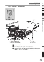
Remove the MAINT DOOR UNIT or the MAINT DOOR C on the stations located on both side
of the BALLSLOPE UNIT that needs a replacement sensor.
If necessary, loosen the two upper pan head screws with washers (M4 x 6) to remove the GUARD F.
Unscrew the four pan head screws with washers (M5 x 12), that secure the BALLSLOPE UNIT
to the MIDDLE PLATE, remove the pan head screws with washers (M5 x 12), disconnect the
harness connectors, and remove the BALLSLOPE UNIT that needs a replacement sensor.
Unscrew the pan head screws with washers (M4 x 6) to remove the SLOPE BRACKET C.
Remove the hexagon nut with flange (M3) that secures the sensor.
Notes
• The sensor module consists of a transmitter and a receiver.
• When the machine is assembled, the JACKPOT SENSOR is for the jackpot win pockets, and the
SLOPE SENSOR is for the normal win pocket.
Содержание PAC-MAN SWIRL
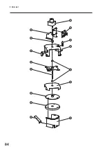
Страница 84: ...9 Parts List 84 27 29 28 18 19 25 26 24 21 23 22 28 31 20 30...
Страница 88: ...9 Parts List 88 39 31 40 29 25 26 22 27 34 23 35 24 21 28 37 20 30 38 32 36 33 40...
Страница 96: ...9 Parts List 96 9 5 Core Assembly 8 7 6 7 5 3 2 9 10 14 11 13 15 14 12 4 1 6 8...
Страница 98: ...9 Parts List 98 34 35 23 17 32 29 16 27 26 28 36 24 17 18 25 19 31 32 32 32 33 30 37 21 20 22 33...
Страница 104: ...9 Parts List 104 9 6 Cabinet Base Assembly 7 15 8 9 10 11 13 6 14 14 10 8 9 8 1 2 12 3 13 14 5 4 13...
Страница 108: ...9 Parts List 108 9 7 Acrylic Door Assembly 22 14 22 13 12 15 20 1 8 6 11 3 16 22 18 17 19 9 10 4 5 7 1 2 21...
Страница 112: ...112...
Страница 122: ......
Страница 123: ......
Страница 124: ......
Страница 125: ......


