10
9
S
Motor and Attachment Operation
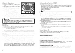
1. Installation and Removal of Burs
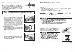
Open the chuck by turning the Bur Lock Ring to the open
position. The chuck is open and the bur can be removed. Install
the new bur and turn the Bur Lock Ring in the Lock direction.
Finally turn the Bur Lock Ring all the way to the Lock position
until it clicks. (
Fig.8
)
Fig. 8
2. Cleaning and Replacement of the Chuck
(1)Removal of the Chuck
Open the Bur Lock Ring and turn the chuck counterclockwise
until you can remove the chuck. Normally, the chuck can be
removed and replaced by hand; if it is too tight use the
included wrench to remove it as shown in the picture (
Fig. 9
)
*Occasionally, when using a large diameter bur at high torque, the chuck may
gradually tighten making it difficult to remove. In this case align the spindle's
wrench flats in the nose's slits and use the provided L wrench to hold the
spindle. Open the Bur Lock Ring and turn the chuck counterclockwise with
the provided chuck wrench to remove the chuck. (
Fig. 10
)
(2)Cleaning the Chuck and Spindle
Remove and thoroughly clean the chuck and ID of the spindle
to maintain accuracy. Remove the chuck and clean the chuck
and spindle ID at least once a week.
(3)Installation and Adjustment of the Chuck
Apply a thin coating of oil to the chuck before installation.
Open the Bur Lock Ring, insert a dummy bur cr cutting tool
into the chuck and then turn the chuck clockwise by hand until
it stops. Next, turn the chuck back, counterclockwise, about
1/5 of a turn to allow the bur to be easily released when the
chuck is open. Finally, turn the Bur Lock Ring until it clicks,
Iocking the bur in place. (
Fig. 11
)
* The chuck's clamping force can be adjusted as shown in
Fig. 11
, if the bur
slips or the bur can not be removed, make adjustments as shown above.
Fig. 9
Loosen
Fig. 10
Loosen
Fig. 11
Turn until finger-tight
1/5Turn
1/5Turn
1/5Turn
CAUTION
Never turn the Bur Lock Ring while the motor is rotating. Turning the Bur Lock Ring
with the motor rotating can cause injury and damage to motor and attachment.
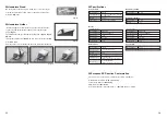
LOCK
OPEN
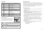
Fig. 12 Removal
Fig. 13 Connecting
Motor Cord Nut
Loosen
3.Disconnecting and Connecting the Motor Cord to the Motor
Removal
• Turn the motor cord nut counterclockwise and remove the cord. Hold the motor nut only when
disconnecting the motor cord; do not pull on the motor cord.
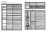
4.Removing the Handpiece from the Motor.
The Handpiece and Motor are screwed together at the rear of
the Handpiece. Hold the motor body and attach the provided
pin wrench to the rear of the Handpiece. Turn the pin wrench
counterclockwise and unscrew the Handpiece. (
Fig. 14
)
Connecting
• Carefully align the pins on the motor with the holes on the motor cord connector and gently push
the motor cord connector onto the motor.
• Tighten the motor cord nut by turning clockwise until it is tight.
CAUTION
To connect the Handpiece to the Motor, turn the
Handpiece clockwise and tighten firmly. If the drive
connections do not align properly, you will not be
able to turn the attachment more than two turns. If
this happens, DO NOT FORCE. Unscrew the
attachment slightly and turn the bur by hand until
the drive connections align, and then screw the
motor and attachment together. (Fig. 15)
Fig. 14
Loosen
Fig. 15
Transmission Clutch
CAUTION
• Do not remove the motor cord except when exchanging the motor cord.
• Be careful not to lose an o-ring between the motor and the motor cord
when exchanging the motor cord.
• Be very careful to push the motor cord connector straight into the motor.
The motor pins can be bent easily and cannot be bent back.
Содержание Emax EVOlution
Страница 1: ...OM K0572E 003 2015 12 04 005 A ...


