11
CD5x
13 CD5x Introduction and Installation
The CD5x CD Player can be operated either from its internal power supply only or, for
improved performance, with an additional external naim Flatcap 2x (or 2) or Hi-Cap
power supply. Connection of the power supply is illustrated in Diagram 14.2. CD player
control and operation is described in sections 19, 20 and 21.
The CD5x should be installed on a dedicated equipment stand intended for the purpose.
Do not stand the player directly on top of another item of naim audio equipment. Care
should be taken to ensure that the player is level.
a transit screw on the underside of the CD5x case should be removed before use and
must be replaced if the unit is to be re-packed and shipped. This transit screw must not
be used in any other naim product. Do not invert the player once the transit screw is
removed.
The player (and external power supply if used) should be installed in its final location
before connecting cables or switching on. ensure that power amplifiers are switched off
and the preamplifier volume is turned down before the player (or external power supply)
is switched on. The player power button is located on the rear panel. The Flatcap 2x
Power supply power button is located on its rear panel. The Hi-Cap Power supply power
button is located on its front panel.
14 CD5x Connections
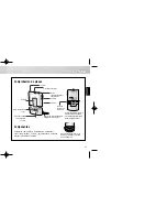
14.1 rear Panel
ch1
-ve
nc
nc
ch2
CD5x
DIn output
notes
The power supply link plug should be fitted unless an
external upgrade power supply is in use.
The RC5 Input is intended to accept external control
signals for multi-room applications. Contact your dealer or
Naim Audio directly for further information.
The optional RJ45 socket Comms Interface can provide
external control of the player in custom installations.
Contact your dealer or Naim Audio directly for further
information.
Phono
output
right
Mains in-
put and
fuse
Power
switch
Comms
interface
RC5 input
Power supply link plug
and upgrade sockets
(link plug fitted)
DIN output
Phono
output
left


