background image


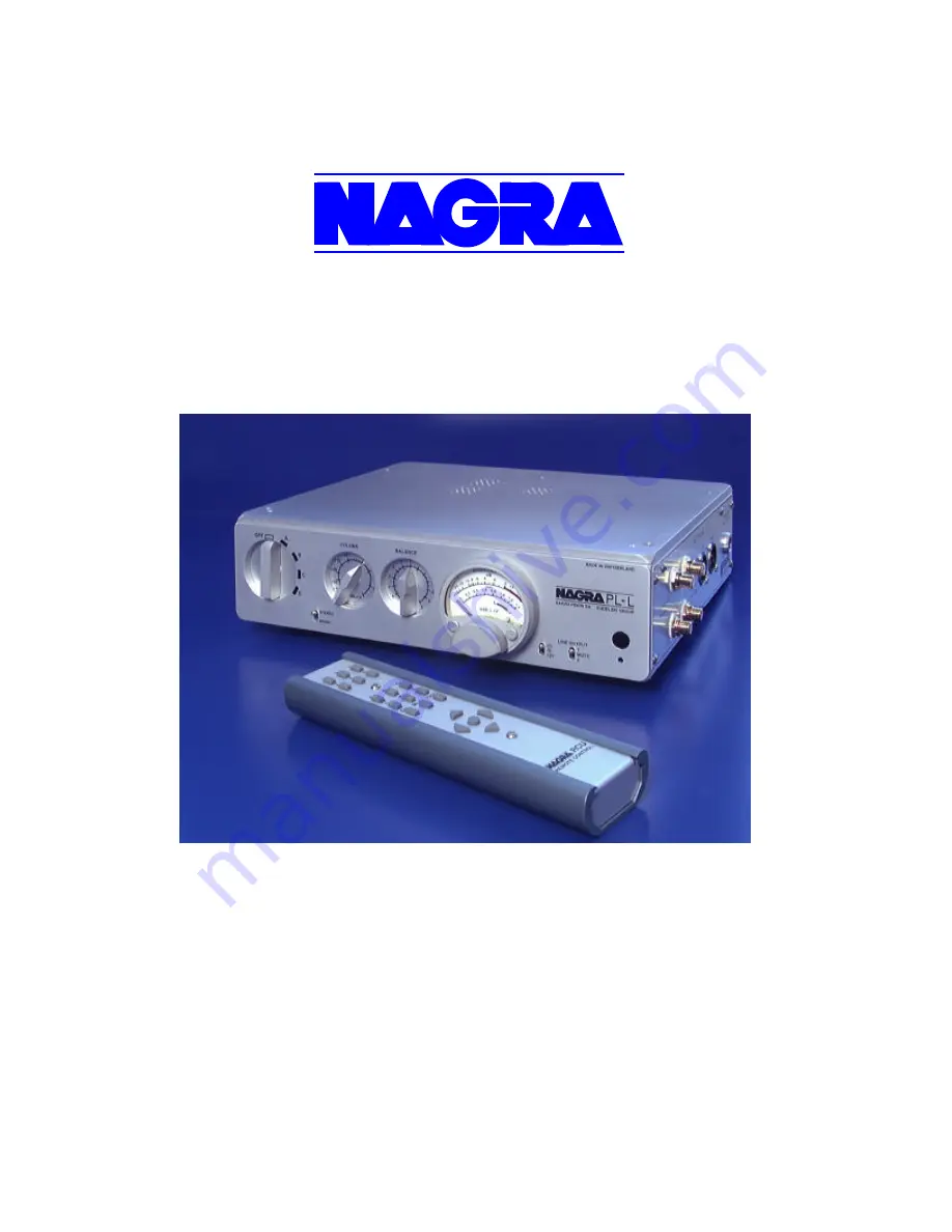
Nagra PL–L Preamplifier 


Owner’s Instruction manual 


NAGRAVISION SA KUDELSKI GROUP 

Route de Genève 22 

CH-1033 Cheseaux 

Switzerland 


Phone +41 (0) 21 732-0101 

Fax +41 (0) 21 732-0100 

E-mail info@nagra .com 


All rights reserved – © May 2003 

(P/N: 2055002151) 

Содержание PL-L

Страница 1: ...fier Owner s Instruction manual NAGRAVISION SA KUDELSKI GROUP Route de Gen ve 22 CH 1033 Cheseaux Switzerland Phone 41 0 21 732 0101 Fax 41 0 21 732 0100 E mail info nagra com All rights reserved May...

Страница 2: ...Identification and Location 8 Remote Control 10 Tube Jumpers and timer positions 12 Burn in Period 12 Left Panel Input Layout 13 Front Panel Control Layout 13 Right Panel Output Layout 15 Advanced Ope...

Страница 3: ...itary businesses Since its inception in 1951 Nagra products continue to earn a reputation f or delivering the best possible sonic and mechanical performance under many very difficult operating conditi...

Страница 4: ...ht costs as well as customs duty and other possible charges are at the customer s expense Our warranty remains valid in the event of emergency repairs or modification being made by the user However we...

Страница 5: ...precision modulometer provides the facility to accurately monitor match and balance output levels o The outputs of the PL L are directly coupled to the output vacuum tubes for the highest audio perfo...

Страница 6: ...el of the PL L is set to OFF The male Lemo connector of the ACPS AC power supply unit can be connected to the female input socket marked POWER IN on the right side panel of the PL L The Lemo connector...

Страница 7: ...nput Voltage 90 132 and 180 264 Volts AC o Frequency 50 60 Hz If the PL L does not turn ON this indicates that a faulty condition exists with the following possibilities The male Lemo connector of the...

Страница 8: ...ance Two types of vacuum tubes are used o 12 AT 7 ECC 81 o 12 AX 7 ECC 83 Many variants of these vacuum tube types are available and may function in the PL L However proper selection and use of vacuum...

Страница 9: ...bes became unseated in transit please refer to the following diagram to identify the vacuum tube required at each socket position and place them in the manner described above The PL L is also furnishe...

Страница 10: ...justments Mute Pressing once on the mute button the PL L output is muted Pressing once the line input A to D button the outputs are enabled ON OFF When the OFF button is pressed the PL L switches to t...

Страница 11: ...om the PL L following the instructions described under paragraph Vacuum Tube Identification and Location Locate the Remote receiver board in the right corner towards the front panel Locate the 5 jumpe...

Страница 12: ...allow all components within the circuits to reach a level of operating equilibrium At the end of this period the mechanical and sonic performance of the PL L will have had an opportunity to reach its...

Страница 13: ...round post is provided for the connection of a ground source to eliminate possible ground loops which can lead to hum To connect input sources ensure that the PL L is powered off or muted and insert t...

Страница 14: ...and pops and surge voltages at the output stage This stays identical if from power off line B C or D was selected LINE B Line B input is selected Power is supplied to all active electronic stages LIN...

Страница 15: ...tion the needle indicates the correct DC input voltage green area Factory adjusted for 12V green area center position o Line Mute switch This is a 3 position switch The functions are as follows In the...

Страница 16: ...internal jumpers for output level is covered in Configuration guidance Output Customization To gain access to the inside of the PL L case ensure that the PL L is powered off disconnect the ACPS power...

Страница 17: ...s into consideration the strongest positive or negative value It is equipped with a memory so that with very brief signals the pointer advances and stays for a sufficient time in order for a reading t...

Страница 18: ...he power supply o A written legend 0 dB 1 0 V printed on the lower center portion of the dial on the instrument reminds the user that all markings are referenced to 0 dB 1 0 Volt on the output connect...

Страница 19: ...signal at Line A Line B Line C or Line D input connectors will register 0 dB on the modulometer scale and produce a 1 0 V output signal at the output connectors factory adjusted Block diagram Output...

Страница 20: ...ched in principle without any risk Normally these two wires carry an identical current one being the return of the other The third wire the ground earth allows all the chassis of all the equipment in...

Страница 21: ...re installation from one single wall socket and avoid connecting any equipment that is not linked to the installation to this power source i e spotlights etc In this example both the humidifier and th...

Страница 22: ...lowest power consumer Equally the units using high level audio signals together and those with lower levels together as indicated in the diagram below CORRECT connection diagram These few basic indica...

Страница 23: ...0 dB out 25 Vrms Dynamic range 100 dB 12 dB output Bandwidth 20 Hz 100 kHz 0 1 dB Distortion 0 02 1 V out no load at 1 kHz 0 10 2 V out 600 Ohm load Physical 2 12AX7 ECC83 Vacuum tubes 1 12AT7 ECC81...

Страница 24: ...rminal EN 61000 4 3 Immunit aux champs lectromagn tique EN 61000 4 3 Immunity to electromagnetic fields EN 61000 4 2 Immunit aux d charges lectrostatiques EN 61000 4 2 Immunity to electrostatic discha...

Страница 25: ...UDELSKI S A CHESEAUX SWITZERLAND All specifications contained in this publication are subject to change at any time without prior notice following improvements and or modifications of the equipment CO...

Отзывы: