


INSTALLATION MANUAL
EN
cable (OUT) with a female connector (Ref. C of figure 1) and a power
supply cable (Ref. F of figure 1). The
MOOD HE TDM
and
MOOD SHE
TDM
configurations have a built-in TouchDimmer switch (ref. E of figure
1).
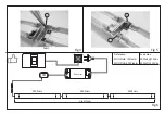
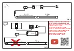
Therefore, installation can include a SET of luminaires connected in a
continuous row with only one power supply cable connected to the first
luminaire (master) which also supplies power to the cascade-connected
luminaires. The continuous row connection cannot exceed the
maximum load of 30W @12Vdc (for HE 120 LED/metre configured
luminaires) and 60W @24Vdc (for SHE 240 LED/metre luminaires).
Installation in a continuous row that includes a luminaire with a TDM
(TouchDimmer master) switch must be carried out connecting said
luminaire at the head of the row and connecting it to the power supply
cable.
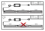
MOOD TDM
can be installed only individually or as the MASTER
luminaire of a continuous row SET. For correct operation of the
TouchDimmer switch, more than one
MOOD TDM
luminaire cannot be
connected in a continuous row. Moreover,
MOOD TDM
may not be
connected to a converter that is connected to a socket controlled by an
electronic or dimmer wall switch. It is also not advisable to connect
MOOD TDM
to a socket controlled by a standard switch.
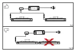
INSTALLATION OF A SINGLE LUMINAIRE
- Secure the clips (A) to the installation surface using the screws (B)
provided in the package as illustrated in figure 1.
- Using pliers, break one of the four membranes (G) on the closing head
located on the side of the intake cable (IN) to run the power supply
cable as illustrated in figure 2.
- Connect the power supply cable (F) to the intake cable (IN) connector
WARNING:
Safety is guaranteed is these instructions are followed and therefore
they must be kept. Installation may require the involvement of qualified
personnel. Before proceeding with installation of the device ensure that
the environmental conditions are in compliance with and suitable for
the product characteristics. Before any operation on the device
disconnect mains power.
CONFIGURATIONS
The installation and operation instructions in this manual are valid for
all configurations of the
MOOD
luminaire, between which there are
some differences. The
MOOD HE
model and
MOOD HE TDM
model
(which has a built-in TouchDimmer master switch) refer to the luminaire
configurations with 120 LED/metro. The
MOOD SHE
model and
MOOD
SHE TDM
model (which has a built-in TouchDimmer master switch)
refer to the luminaire configurations with 240 LED/metro. The parts of
this installation and operation manual common to all models refer to
the
MOOD
model, in other words, the luminaire configuration that does
not have the built-in switch.
INSTALLATION
MOOD
luminaires are recommended for installation under hanging
kitchen cabinets or under shelves. The installation can be carried out
with the luminaire power supply cable in both an axial or radial position
with respect to the installation surface. In the event of a specific
requirement these luminaires can nevertheless be installed in other
positions as long as it does not compromise the integrity of the wire
and/or the connector installed on it. Each
MOOD
luminaire has an
intake cable (IN) with a male connector (Ref. D of figure 1), an output


