


(Revised 2012-05-01)
Page 16 of 163
N-TRON SWITCH GROUNDING TECHNIQUES
The grounding philosophy of any control system is an integral part of the design. N-Tron switches are
designed to be grounded, but the user has been given the flexibility to float the switch when required. The
best noise immunity and emissions (i.e. CE) are obtained when the N-Tron switch chassis is connected to
earth ground via a drain wire. Some N-Tron switches have metal din-rail brackets that can ground the
switch if the din-rail is grounded. In some cases, N-Tron switches with metal brackets can be supplied with
optional plastic brackets if isolation is required.
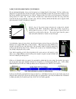
Both V- legs of the power input connector are connected to chassis
internally on the PCB. Connecting a drain wire (shown in green) to
earth ground from one of the V- terminal plugs as shown here will
ground the switch and the chassis. The power leads from the power
source should be limited to 3 meters or less in length.
As an alternate, users can run a drain wire (shown in green) & lug from any of the Din-
Rail screws or empty PEM nuts on the enclosure. When using an unused PEM nut to
connect a ground lug via a machine screw, care should be taken to limit the penetration
of the outer skin by less than 1/4 in. Failure to do so may cause irreversible damage to
the internal components of the switch.
Note: Before applying power to the grounded switch, you must use a volt meter to verify
there is no voltage difference between the power supply’s negative output terminal and
the switch chassis grounding point.
If the use of shielded cables is required, it is generally recommended to only connect the shield at one end to
prevent ground loops and interfere with low level signals (i.e. thermocouples, RTD, etc.). Cat5e cables
manufactured to EIA-568A or 568B specifications are required for use with N-Tron Switches.
In the event all Cat5e patch cable distances are small (i.e. All Ethernet devices are located in the same local
cabinet and/or referenced to the same earth ground), it is permissible to use fully shielded cables terminated
to chassis ground at both ends in systems void of low level analog signals.
Содержание 712FX4 Series
Страница 1: ...712FX4 Managed Industrial Ethernet Switch User Manual Installation Guide...
Страница 11: ...Revised 2012 05 01 Page 11 of 163 CLEANING Clean only with a damp cloth...
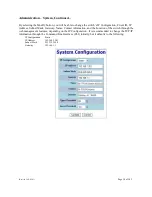
Страница 33: ...Revised 2012 05 01 Page 33 of 163 Administration SNMP Continued...
Страница 37: ...Revised 2012 05 01 Page 37 of 163 DHCP Server Setup Profiles Continued...
Страница 40: ...Revised 2012 05 01 Page 40 of 163 DHCP Server Setup IP Maps Continued...
Страница 46: ...Revised 2012 05 01 Page 46 of 163 DHCP Relay Local IP Setup Continued...
Страница 52: ...Revised 2012 05 01 Page 52 of 163 Ports Configuration Continued...
Страница 82: ...Revised 2012 05 01 Page 82 of 163 IGMP RFilter Continued Modifying rfilter port settings...
Страница 90: ...Revised 2012 05 01 Page 90 of 163 N Ring Advanced Configuration Continued...
Страница 113: ...Revised 2012 05 01 Page 113 of 163 If a Configuration Device is present that is presented...
Страница 149: ...Revised 2012 05 01 Page 149 of 163...


