


connected to an appropriate Sensor, and that the Sensor is
immersed in water within the range that the Monitor/controller will
be required to read; and the front panel is removed.
1. Make a note of the reading on the display.
2. While pressing the Calibration/Full Scale Test Switch
(FSSW), verify that the front panel display is indicating
a full scale reading. If not, see Calibration, section V.C.
3. Press and hold the “SET POINT” switch on the front
panel. Using a tweaker or a small screwdriver, adjust
the Set Point trimmer adjustment screw on the circuit
board to sweep the display from zero to full scale. (A
digital display may be blank at the full scale end. This
is normal.) Listen for the alarm relay to click on and off
as the alarm set point moves past the water reading.
4. Adjust the alarm to the desired set point value. Release
the “SET POINT” switch.
NOTE:
For Models with SC/SCO module, repeat STEPS 3 & 4 to
check out Set Point #2.
QUICK SET POINT ADJUSTMENT -
See Section IV.C.3.
The set point setting is based upon the user’s particular water
purity specifications or requirements.
NOTE:
The optional
second
relay/alarm is “stacked” on the first relay/alarm,
therefore, when setting the optional
second
relay/alarm Set
Point, the #1 Set Point must be ‘set’ first.
1. While pressing the “SET POINT” switch, turn the Set
Point #1 adjustment screw (see figure V.A.1) until the
desired set point value is indicated on the display.
HYSTERESIS (DEAD BAND) ADJUSTMENT -
See Section IV.C.4.
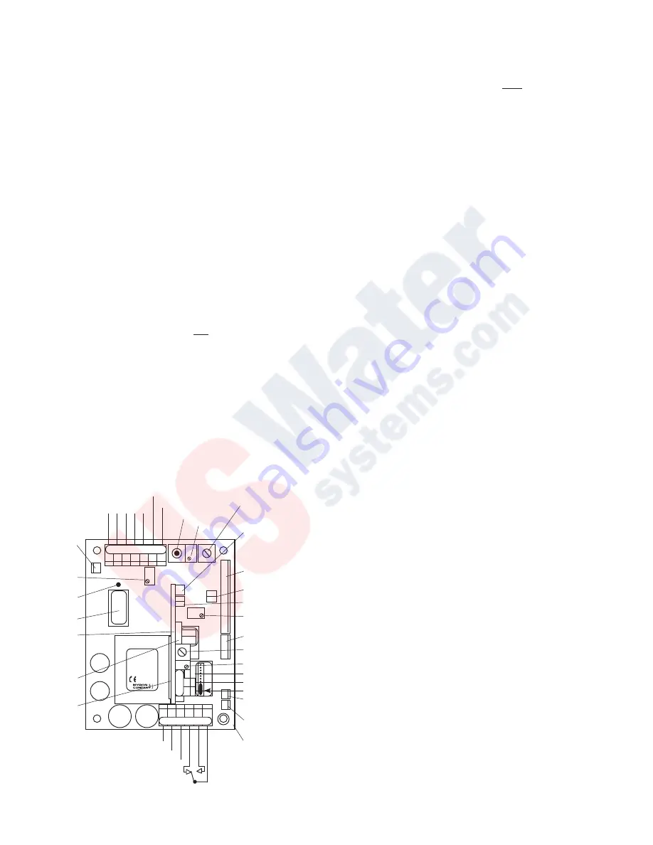
PRIMARY COMPONENT IDENTIFICATION -
Section V.A.
Review the figure below to familiarize yourself with the Main
circuit board assembly. The diagram has the second alarm/
control module option installed.
QUICK CALIBRATION - Section V.C.
WARNING: When performing calibration procedures,
the technician must take extreme care to avoid
contacting the circuitry other than the CALibration
control. Failure to do so could result in damage to
the equipment, property and/or personal injury.
The following assumes the front panel has been
removed and the power is ON.
ELECTRONIC CALIBRATION (CIRCUIT ONLY) -
See Section V.C.1.
Full Scale Adjustment
1. Press and hold the Full Scale Test switch. The display
should indicate Full Scale for the particular range
selected, i.e. 0-500 ppm should indicate 500. If not, set
to Full Scale with the
CAL
ibration control.
2. Turn power
OFF
.
3. Re-install front panel as described in “REASSEMBLY”.
4. To operate, turn power
ON
.
10VDC Calibration - See Section V.C.1.b.
Using Standard Solutions - Section V.C.2.
The
BEST
method of verifying and recalibrating your
conductivity/TDS Monitor/controller is with NIST traceable
Standard Solution (available from the Myron L Company).
Because it includes the sensor, the entire system is recalibrated.
NOTE:
Since standard solution calibrations are NOT practicable
with resistivity models, another means of verification or
calibration of resistivity models is to use the transfer standard
method, using a hand-held or portable instrument capable of
resistivity measurements, i.e. the Myron L Ultrameter
II
™. See
section V.C.4 for description.
The following procedure describes the easiest method for
standard solution calibration of your Conductivity/TDS
Monitor/controller.
1. Using a standard solution which is 60-90% of full scale
of the instrument, rinse thoroughly and fill a clean glass
beaker with the standard solution.
2. Place sensor in the beaker of standard solution. The
level of standard solution must be high enough to cover
at least 1/2” above cross hole.
3. Slowly shake the sensor to remove air bubbles from
inside the sensor bore hole.
4. Allow 5-10 minutes for temperature to equilibrate. For
the quickest and the best results, both the sensor and
solution should be at the same temperature.
5. Turn power
ON
.
6. If the reading is different from the standard solution,
adjust
CAL
ibration control on the main circuit board
until the reading matches the solution value.
7. After adjustment, turn power
OFF
.
8. Re-install front panel as described in “REASSEMBLY”.
9. To operate, turn power
ON
.
SENSOR SUBSTITUTE CALIBRATION -
See Section V.C.3.
TRANSFER STANDARD METHOD - See Section V.C.4.
B
L
K
W
H
T
SENSOR
RANGE
MODULE
MAIN
CALIBRATION
CONTROL
SC/SCO
OPTIONAL
SECOND
ALARM/
CONTROL
MODULE
#2 RELAY
LIGHTS &
SWITCH
CONNECTOR
RUBBER TAPE
(DO NOT
REMOVE)
RANGE
MODULE
ALIGNMENT
3SO/3SE
&/OR
3RO/3RE
SWITCH
OR
FLOW SWITCH
CONNECTION
POWER
AC LINE/ +DC
AC NEUTRAL/ -DC
GROUND
RELAY #1
}
COM
NC
NO
DISPLAY/METER
CONNECTOR
4-20 CONNECTOR
SET POINT #1
CONVERSION
SET POINT #2 CONTROL
SET POINT #2
CONVERSION
DISPLAY CALIBRATION
CONTROL (FACTORY SET)
SET POINT #1
HYSTERESIS
RIGHT INC
LEFT DEC
CHASSIS GROUND - OEM
SET POINT #2 HYSTERESIS
RIGHT INC / LEFT DEC
SOLID STATE (24VDC 30mW)
OUTPUT
PA™ PIEZO ELECTRIC ALARM
OR
RA™ REMOTE ALARM OR
CUSTOMER CONNECTION
SOLID STATE (24VDC 30mW)
OUTPUT
RA™ REMOTE ALARM AND
PA™ PIEZO ELECTRIC ALARM
OR
CUSTOMER CONNECTION
RELAY #2
}
COM
NO
NC
FULL SCALE
PUSH TO TEST
SET POINT
#1 CONTROL
0-10VDC OUTPUT
N
E
U
(+)
(-)
R
E
D
G
R
N
3S
PA
HYS1
SP1
FS SW
DIS
INC
DEC
CAL
INC
-121
2000µS
}
SPC
TRANSFORMER
FUSE*
115/
230
751 756
752 757
753 758
754 759
CHS
GND
PWR
C GD NC NO CM
C
M
N
O
N
C
SPC
INC
UP
+
+
PA
RA
{
BK WT RD GN NU R- R+
REMOVE T
O INST
ALL
SECOND RELA
Y
5/21/03
Figure V.A.1