background image


RC4 decoder   V2.0. - October 2017 


© MYLAPS rights reserved

  15


Sub menu 

Click on the select button to go to Menu and click on the acknowledge button to go to the submenu. Click on the select 
button to go to down in the menu. When you got the right submenu, click on the acknowledge button again to set the 
information. 

Timeline 

Name 
Index 
Main/back up  

With these settings, you can define the role of the decoder.  The settings do not influence the decoder 
performance but can be retrieved by the software for easier track setup. If multiple intermediate points 
are used the Index can be used to set the order of the intermediate points. 

Squelch 

With the squelch setting you can suppress weak transponder signals. This is sometimes useful if cars or 
drones are near the loop or the coaxial cable and are picked up accidently. E.g. if the squelch setting is 
set to 150 all transponders with received strength below 150 will be ignored. 

Car id Squelch 

Time interval after the detection of a transponder, in which identical transponder numbers, but with a 
different CarId, will not be detected. (Not applicable for RC4 compatible timing software) 

General 

Decoder Mode 

Choose if you want to use drone or RC 
 

Clear passings 

Enables you to clear the passings in the flash memory. 

Clock 

Date: Here you can change the date. 
Time: Here you can change the time of day.  
To set your decoder to a specific time in seconds: First select the time in hours and minutes that you 
wish to set the decoder on. After this, the decoder will ask you to select SET. At the exact moment SET 
is selected, the decoder clock will start at the selected time from zero seconds. For example: the new 
time setting for the decoder is 11.15; when you press SET, the decoder clock will start counting at the 
exact time, 11h:15m:00s. 

Beep 

Choose the tone of the beep. 

Protocol RS232 

This is used to select the protocol on the RS232 interface. Applies to both RC4 and DR5 transponders. 
There are 3 options: 
Enhanced - This protocol is here only for compatibility reasons. Not all features are available via this 
protocol. 
P3 - If you are a software developer this is the preferred protocol to use. This protocol is also used for 


Remote - Allows the host computer to select the protocol by using a command. Use this setting when 
used with Orbits. 

Contrast 

Contrast of the display - Here you can adjust the contrast settings. 

Factory defaults 

Reset to the factory defaults - You can reset the settings of the decoder to the initial settings. 

Firmware 

Software running inside the decoder - When you update the firmware in your decoder, the decoder 
will retain the current version of the firmware. With the switch decoder firmware option you can revert 
back to the previous version.   

Network 

Please leave the decoder in the automatic menu if you are not familiar with network basics. 
 

Automatic 

To automatically determine the IP address of the decoder. If your decoder is placed in a network and 

Configuration Protocol) to get an IP address which is in the range of the network. Please note that it 
can take about 60 sec. to obtain the settings via DHCP. If a DHCP server is not found, the decoder will 
use an IP address via APIPA (Automatic Private IP Addressing). 

IP Address 

IP address of your decoder - An identifier for a computer or device on a TCP/IP network.  

Subnet Mask 

A mask used to determine what subnet an IP address belongs to. 

Gateway 

A node on a network that serves as an entrance to another network. 

DNS 

Short for Domain Name System (or Service or Server), an Internet service that translates domain names 
into IP addresses. Gateway and DNS are both used to set up the decoder for  MYLAPS Practice. 


Содержание RC4

Страница 1: ...ENGLISH MANUAL RC4 DECODER PRODUCTCODE 40R248 VERSION 2 0 ...

Страница 2: ...vice complies with part 15 of the FCC rules Operation is subject to the following two conditions 1 This device may not cause harmful interference and 2 This device must accept any interference received including interference that may cause undesired operation RF Exposure OET Bulletin 65 To comply with FCC RF exposure requirements for mobile transmitting devices this transmitter should only be used...

Страница 3: ...tware Development Kit is a custom made product by a third party About this Manual This manual is intended for operating and supervisory personnel and provides information on installing and operating the RC4 decoder This publication has been written with great care However the manufacturer cannot be held responsible either for any errors occurring in this publication or for their consequences The s...

Страница 4: ... RC4 Decoder 7 2 3 Installation of the RC Timing system 8 Positioning the detection loop RC Racing 9 Positioning the detection loop Drone Racing 11 2 4 Operating the MYLAPS decoder 12 2 5 Noise level 12 2 6 Signal strength 12 2 7 Number of hits 12 2 8 Firmware update 12 2 9 The decoder 13 2 10 Menu 14 3 Appendix Auxiliary connections 17 4 Support 19 CE Declaration of Conformity MYLAPS RC4 Decoder ...

Страница 5: ...s timing software and DR5 and RC4 transponders Every pilot owns or rents a lightweight transponder that is mounted onto the drone The transponder sends out a unique signal so there is no video signal erroring When pilots register the transponder to their MYLAPS Speedhive account they get an overview of all their training and race data When you already own a MYLAPS RC4 decoder you can convert it to...

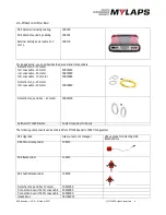
Страница 6: ...ction loop 20 meter Incl coax cable 20 meter 30R001RC 30R002RC 30R003RC 30R004RC Detection loop end box 20 meter 30R011RC Software MYLAPS Practice Custom made by third party The following components can be ordered from MYLAPS as part of RC4 Timing system RC4 Upgrade Ask your account manager V4 5 upgrade for detecting DR5 transponders DR5 Drone transponder 10R213 RC4 transponder 10R120 RC4 hybrid t...

Страница 7: ...a GPS receiver to UTC Max track width max 20 m 66 ft Operating temperature range 20 to 50 C 4 to 122 F Humidity range 10 to 90 relative Operating voltage range 10 to 14 4 V typical 12V Power consumption max 650 mA 12V typical 500 mA Interfaces RS232 9600 baud 8 bits 1 stopbit RJ45 10 100 BaseT USB A Network connection DHCP client APIPA Static IP Aux Power 5 VDC max 100 mA Aux Output Opto coupled c...

Страница 8: ...PS RC decoder The decoder timestamps the received transponder signals and sends this data to a connected computer Each transponder has a unique number which enables you to identify and time score each RC car on the track The MYLAPS decoder is a precision instrument Therefore please handle it with care and keep the decoder out of direct sunlight and avoid high humidity Take special precautions in c...

Страница 9: ...und it Now put the shrinkage sleeve over the soldered connection and hold it over a heat source to shrink the sleeve also see 5 the drawing on the next page Repeat this procedure for the second wire end of the detection loop 3 Fill the slot with silicone Make sure not to overfill the slots and that the silicone is fully under the surface of the track otherwise tires may pull out the silicone If an...

Страница 10: ...utside the bridge 8 2 Wires of the loop must be 45cm 1 5ft apart and fixed underneath the bridge Put the connection box on top of the bridge Solder all connections and insulate well Please keep in mind that since a bridge has a larger distance between detection loop and passing transponder this results in a weaker signal for the decoder At dawn and at night the interference from short wave radio s...

Страница 11: ...You can determine if your loop is functioning correctly by doing the following tests 1 Connect the detection loop to the decoder and computer running MYLAPS timing software Check the background noise which is updated every 5 seconds in the MYLAPS timing software The background noise level should be between 0 and 40 points A higher value may indicate a bad loop installation or interference by other...

Страница 12: ...ise is higher than 40 points make sure that the signal strenght of the transponder is at least 60 points higher that the noise level 4 2 Signal strength Transponder signal strength as shown by the timing software and on the decoder screen should preferably be above 100 points and should at least be 60 points higher than the indicated background noise The closer the transponder is to the track the ...

Страница 13: ...to connect the network cable between the decoder and the network connection port of the computer 5 Power Connect the supplied VDC adapter to the decoder and mains It is recommended to connect the VDC adapter to mains through a UPS Uninterruptable Power Supply to avoid any interruption of power supply to the decoder Front side 1 USB port 2 Headphone A beep will sound for every passing transponder w...

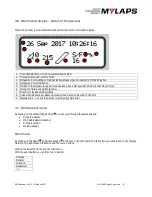
Страница 14: ...ceived transponder 7 Number of received GPS satellites 8 Links when GPS receiver attached steady when decoder is locked to UTC time 9 Message line You will see errors or warnings E g DNS error 4 7 RC4 decoder menu By clicking on the acknowledge button you will cycle through the status screens Active IP Address MAC Address serial number Firmware version Stored passings Main menu By clicking on the ...

Страница 15: ... decoder clock will start counting at the exact time 11h 15m 00s Beep Choose the tone of the beep Protocol RS232 This is used to select the protocol on the RS232 interface Applies to both RC4 and DR5 transponders There are 3 options Enhanced This protocol is here only for compatibility reasons Not all features are available via this protocol P3 If you are a software developer this is the preferred...

Страница 16: ...ss of a server to upload data to Port TCP IP port where the server receives the data MYLAPS Practice code A unique code which should be used for registering on MYLAPS Practice website www mylaps com practice Please visit mylaps com for more information about online race results Note For accessing server functionality you need a functioning internet connection Also the DNS server and gateway settin...

Страница 17: ...l inputs can be triggered by a 5 VDC 5 15 mA pulse Figure 1 explains the connection setup To use a photocell connect it using the MYLAPS photocell cable or make an appropriate cable using figure 1 below Two types of photocells are available passive and active photocells They both operate as a switch to connect the passive photocells please follow the connection setup in figure 1a and scheme 1b Act...

Страница 18: ...RC4 decoder V2 0 October 2017 MYLAPS rights reserved 18 ...

Страница 19: ...Email info mylaps com MYLAPS Americas Office Atlanta USA Tel 1 678 816 4000 Email info americas mylaps com MYLAPS APAC Office Sydney Australia Tel 61 2 9533 1100 Email info asia pacific mylaps com MYLAPS Japan Office Tokyo Japan Tel 81 3 6418 8209 Email info japan mylaps com MYLAPS Asia Office Selangor Malaysia Tel 60 3 5613 1235 Email info asia mylaps com MYLAPS 24 7 Only in cases of direct neede...

Страница 20: ...EC Radio Telecommunications Terminal Equipment Directive Has been designed and manufactured to the following specifications EN 301 489 1 2005 09 EN 301 489 3 2002 08 EN 302 208 2 2008 04 EN 61000 3 2 2006 EN 61000 3 3 2008 I hereby declare that the product named above is designed to comply with the relevant sections of the above referenced specifications and all essential requirements of the Direc...

Отзывы: