8
Technical Specifications
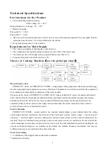
Environment for the Product
*
The surrounding temperature range:
When cutting: -10
~
+40
℃
During transport or in storage: -25
~
+55
℃
*
Relative humidity:
When at 40°C
: ≤
50%
When at 20°C:
≤
90%
*
The dust, acid and erosible materials in the air can not exceed the amount required by the norm (apart from the
emissions from the cutter ). No violent vibration at the job site.
*
Keep from raining when it is used outdoor.
Requirement for Main Supply
*
The voltage oscillogram should display actual sine wave.
*
The oscillation of the supplied voltage should not exceed ±20% of the rated value.
*
The imbalance rate of three phases main supply should not less than 0.5%.
*
Frequency fluctuation should be less than ± 2%..
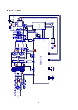
Theory of Cutting Machine
(
see the principle chart
)
The principle chart
POWER CUT Series Air POWER CUT 60/70HF
Ш
is high speed cutting equipment with advanced technology
which is using high density plasma arc as source of the heat. The plasma arc would be acquired by the compressed
air as ionization medium and the compression of the torch’s nozzle.
The main electric theory of POWER CUT 60/70HF
Ш
:400V 3-phase industrial AC power is required, and transfer
to DC after rectified by Single phase rectification bridge and transformed by the middle frequency transformer,
and then rectified to the DC by the fast recovery diode, While starting cutting, the nozzle and electrode are
separated quickly by the air pressure, the voltage between them make the air are ionization and arc which is
moved between work piece and electrode pilots .
Cutter’s Structure
POWER CUT 60/70HF
Ш
applies portable box structure: digital display, protect indictor light, the cutting
current adjust knob,are installed on the first half of the front board; and the current output ‘+’ electrode quick
connector, ‘-’ electrode quick connector, cuttingtorch control(two pins socket), switch socket are installed on the
next half; the power inlet,Impressed gas input connector and power switch, are installed on the back board; the
control transformer,control press circuitry board can be seen on the first installation board after shelling the out
case;the rectification bridge etc. are installed on the bottom, the medium frequency transformer, fast recovery
rectifiers, heat sink etc. are installed in the centre of the box.
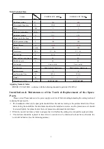
Cutter Type Coding
*
Combination of the English letter and the Arabic numerals.
*
Implication of Coding:


