MW TOOLS 829300196 Скачать руководство пользователя страница 19


19


FR

M1.2.MIG160E-MIG200E.NLFREN   09102018


N2190A SC-A0

groove. Adjust the pressure arm, ensuring no sliding of the wire. Too high pressure will lead to wire 
distortion, which will affect wire feeding. Press the manual wire feeding button to thread the wire out 
of the torch contact tip.

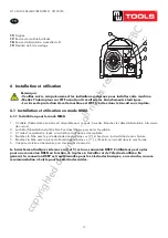
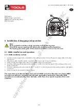
10.2.2 Sketch map of installation

Gas hose

Switching-box

Fig. 8

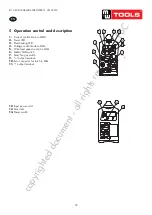
10.2.3 Operation method

1) After being installed according to the above method, and the power switch being switched on, the 

machine is started with the fan working. Open the cylinder valve, and adjust the flow regulator to get 
the proper gas flow.

2) Switch the MMA/MIG switch on the front panel of the machine, and then adjust the “voltage control 

knob in MIG” and “wire feed speed control knob in MIG” on the front panel of the machine to get the 
proper welding voltage and welding current.

3) Push the torch trigger, and welding can be carried out.
4) Adjust the burn-back time potentiometer on the middle plate to get the proper electrode stick-out.
5) 1 second after the arc stops, the gas supply will be cut off.

14

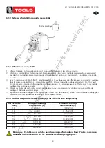
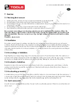
6.2  Installation et utilisation en mode MIG

6.2.1  Installation pour le mode MIG

1. 

Insérez la torche de soudage dans le connecteur Euro (10) , et fixez-la. Après avoir installé la bobine de fil, engagez 

manuellement le fil de soudage dans le corps de la torche.

2. 

Avec un tuyau, branchez la bouteille de gaz équipée d’un régulateur à l’entrée de gaz (13).

3. 

Insérez la fiche du câble avec la pince de travail dans la sortie «-» (11), et fixez-la en tournant dans le sens horaire.

4. 

Insérez la fiche du dévidoir dans la sortie «+» (9), et fixez-la en tournant dans le sens horaire.

5. 

Installez la bobine de fil sur l’axe, en veillant à ce que la taille de la rainure en position d’alimentation sur le galet 

d’entraînement corresponde à la taille de la pointe de la torche et à celle du fil utilisé. Relâchez le bras de pression 

du dévidoir pour engager le fil dans le tube de guidage, et dans la gorge du galet d’entraînement. Réglez le bras de 

pression, en veillant à ce que le fil ne puisse pas glisser. Une pression trop grande peut déformer le fil, ce qui aura 

une influence sur l’alimentation du fil. Appuyez sur le bouton d’alimentation manuelle du fil pour le faire passer dans 

la pointe de contact de la torche.

6.2.2  Schéma d’installation pour le mode MIG

6.2.3  Utilisation en mode MIG

1. 

Allumez l’appareil à l’interrupteur principal. La LED de fonctionnement s’allume et le ventilateur tourne. Ouvrez la 

valve de la bouteille de gaz et réglez le régulateur pour obtenir le débit souhaité.

2.  Mettez le sélecteur MIG/MAG (6) en mode MIG, réglez ensuite la pression souhaité au bouton de réglage (4),  

ainsi que l’alimentation du fil au bouton de réglage (5).

3.  Appuyez sur la gâchette de la torche, et le soudage peut commencer.

4. 

Réglez la distance entre le fil et la pièce au potentiomètre du burnback (17).

5.  L’alimentation en gaz doit être coupée 1 seconde après que l’arc se soit éteint.

Boîtier électrique

Tuyau du gaz

copyrighted 

document 

- all 

rights 

reserved 

by 

FBC

Содержание 829300196

Страница 1: ...300210 Lastoestel Poste de soudage Welding machine P 02 Gelieve te lezen en voor later gebruik bewaren P 13 Veuillez lire et conserver pour consultation ultérieure P 24 Please read and keep for future reference FR EN NL c o p y r i g h t e d d o c u m e n t a l l r i g h t s r e s e r v e d b y F B C ...

Страница 2: ...lding Keep the working environment well ventilated with exhaust or ventilation equipment when welding Een vakopleiding is noodzakelijk om de machine te gebruiken Gebruik lichaamsbeschermingen die voor laswerken aanbevolen worden De gebruiker moet voldoende gekwalificeerd zijn voor las en snijwerken Schakel de machine uit voor alle onderhoud en herstellingswerken Elektrische schok kan zware letsels...

Страница 3: ...ker that noise may be potentially hazardous to hearing Magnetic field can make cardiac pacemaker a bit wonky People with cardiac pacemaker should stay away from the welding spot without first talking to a doctor Moving parts may injure your body Please keep away from moving parts like fan Each door panel cover baffle plate and protective device the like should be closed and located correctly Z210 ...

Страница 4: ...sprestaties Het kan met verschillende electroden met een diameter van 0 6 mm 0 9 mm gelast worden en zowel met zure als met basische elektrodes Eenvoudig starten van de lasboog minder spatten stabiele stroom en goede vormgeving Mooie vorm en betrouwbaar structuur Voor en achter panelen in de vorm van stroomlijn maken het toestel mooier Voor en achter panelen gemaakt van hoge intensiteit kunststoff...

Страница 5: ...trol in MIG 6 MMA MIG switch 7 Gas No gas switch 8 Socket for push pull torch 9 output terminal 10 Euro connector for torch in MIG 11 output terminal 11 10 9 8 7 1 2 3 4 5 6 Fig 3 Hole 1 Push pull torch power source Hole 2 Push pull torch power source Hole 3 9 Null Fig 4 Socket for push pull torch power source and torch trigger 10 12 Voedingskabel 13 Gasinlaat 14 Schakelaar N2190A SC A0 12 Input p...

Страница 6: ...ker met de elektrodehouder in de uitgang 9 aan en draai deze vast 5 Sluit de stekker met de werkklem in de uitgang 11 aan en draai deze vast 6 Een verbinding met de aarde is noodzakelijk voor de veiligheid De aansluiting zoals hierboven in 4 en 5 is de DCEP aansluiting De bediener kan DCEN kiezen in functie van het werkstuk en de elektrode toepassingseisen In het algemeen wordt DCEP aanbevolen voo...

Страница 7: ...an in het bereik van de nominale uitgangsstroom uitgevoerd worden Schakel de MMA MIG omschakelaar 6 naar MIG Ontsteek de boog en las in Lift Arc modus De boog kan in het bereik van de nominale stroom ontstoken worden en het lassen kan in het bereik van de nominale stroom uitgevoerd worden zie afbeelding hieronder 4 Kies een kabel met een grotere doorsnede om de spanningsdaling te verminderen als d...

Страница 8: ...f the torch contact tip 2 2 Sketch map of installation Gas hose Switching box Fig 8 2 3 Operation method After being installed according to the above method and the power switch being switched on the machine is started with the fan working Open the cylinder valve and adjust the flow regulator to get the proper gas flow Switch the MMA MIG switch on the front panel of the machine and then adjust the...

Страница 9: ...Euro connector for torch in MIG output socket on the front panel of he machine and tighten it After install the wire spool manually thread the welding wire into the orch body nsert the cable plug with work clamp into the output terminal on the front panel of the welding machine and tighten it clockwise nsert the quick plug of the wire feeder into the output terminal on the middle plate of the weld...

Страница 10: ... en de levensduur van de machine 7 3 Overspanning is verboden Voor de spanningsbereik van de machine verwijzen we u naar hoofdparameters Die machine is met een compensatie systeem uitgerust die ervoor zorgt dat de spanning binnen een bepaald bereik varieert Als de ingangsspanning te hoog is kunnen componenten van de machine beschadigd worden 7 4 Overlading is verboden Zorg ervoor dat de lasstroom ...

Страница 11: ... de verbindingen en tussen de verbindingen en de behuizing De machine mag opnieuw gebruikt worden alleen wanneer er geen abnormale verschijnselen meer zijn 5 Controleer regelmatig de isolatie van de kabels op perfecte toestand en vervang indien nodig de isolatie of de kabel 6 Als de machine voor een lange termijn niet gebruikt wordt leg deze op in de originele verpakking in een droge plaats 9 Stor...

Страница 12: ...stop De haspel is defect Herstel de haspel De printplaat voor controle of voor de draadaanvoer is defect Vervang de printplaat De lasstroom is onstabiel De drukarm op de haspel is niet correct ingesteld Regel de druk correct De aandrijfrol komt niet overeen met de grootte van de draad Controleer dat de groottes met elkaar overeenkomen Het contactpunt van de toorts is versleten Vervang het contactp...

Страница 13: ...ion equipment when welding 1 Sécurité Une formation professionnelle est nécessaire pour utiliser l appareil Utilisez les protections corporelles recommandées pour le soudage L utilisateur doit être qualifié pour les travaux de soudage et de découpage Débranchez l appareil avant tout travail d entretien et de réparation Choc électrique pouvant causer de graves blessures et même la mort Installez un...

Страница 14: ...aker a bit wonky People with cardiac pacemaker should stay away from the welding spot without first talking to a doctor Moving parts may injure your body Please keep away from moving parts like fan Each door panel cover baffle plate and protective device the like should be closed and located correctly Z210 SC A0 Seek professional support when trouble strikes When trouble strikes in installation an...

Страница 15: ...riété d applications et des performances améliorées de l appareil L appareil convient au soudage avec des électrodes d un diamètre de 0 6 à 0 9 mm acides ou basiques Amorce facile de l arc peu de projections courant stable et bonne mise en forme Bel aspect et structure fiable de l appareil Les panneaux avant et arrière dessinés en forme d ondes rendent l appareil élégant Les panneaux avant et arri...

Страница 16: ... Wire feed speed control in MIG 6 MMA MIG switch 7 Gas No gas switch 8 Socket for push pull torch 9 output terminal 10 Euro connector for torch in MIG 11 output terminal 11 10 9 8 7 1 2 3 4 5 6 Fig 3 Hole 1 Push pull torch power source Hole 2 Push pull torch power source Hole 3 9 Null Fig 4 Socket for push pull torch power source and torch trigger 10 12 Câble d alimentation 13 Entrée de gaz 14 Int...

Страница 17: ...rte électrode dans la borne 9 et fixez la en tournant dans le sens horaire 5 Branchez la fiche avec la pince de travail dans la borne 11 et fixez la en tournant dans le sens horaire 6 Une prise de terre est nécessaire pour des raisons de sécurité Le branchement indiqué ci dessus en 4 et 5 est une connexion DCEP L utilisateur peut opter pour une connexion DCEN en fonction de la pièce à travailler e...

Страница 18: ...type et de la taille de l électrode écrêtez l électrode et le soudage peut commencer Pour les paramètres de soudage voir le tableau ci après 6 1 4 Tableau des paramètres de soudage à titre de référence uniquement Dia électrode mm Courant de soudage recommandé A Tension de soudage recommandée V 1 0 20 60 20 8 22 4 1 6 44 84 21 76 23 36 2 0 60 100 22 4 24 0 2 5 80 120 23 2 24 8 3 2 108 148 23 32 24 ...

Страница 19: ...u câble avec la pince de travail dans la sortie 11 et fixez la en tournant dans le sens horaire 4 Insérez la fiche du dévidoir dans la sortie 9 et fixez la en tournant dans le sens horaire 5 Installez la bobine de fil sur l axe en veillant à ce que la taille de la rainure en position d alimentation sur le galet d entraînement corresponde à la taille de la pointe de la torche et à celle du fil util...

Страница 20: ...etal arc welding Installation method of gasless self shielded metal arc welding sert the welding torch into the Euro connector for torch in MIG output socket on the front panel of e machine and tighten it After install the wire spool manually thread the welding wire into the rch body sert the cable plug with work clamp into the output terminal on the front panel of the welding achine and tighten i...

Страница 21: ...ipaux Le poste à souder est équipé d un système de compensation qui fait varier la tension dans les limites acceptables Une tension d entrée trop élevée peut endommager des composants de l appareil 7 4 La surcharge est interdite Respectez le courant de soudage maximum Assurez vous que le courant de soudage ne dépasse pas la capacité de l appareil Une surcharge peut diminuer la durée de vie de votr...

Страница 22: ...ntre les connections et entre connections et carénage L appareil ne peut être à nouveau utilisé que lorsque tout phénomène anormal a disparu 5 Contrôlez régulièrement l isolation des câbles Si nécessaire remplacez l isolation ou les câbles défectueux 6 Si l appareil n est pas utilisé pendant une longue période rangez le dans l emballage d origine dans un endroit sec 9 Dysfonctionnements AVERTISSEM...

Страница 23: ...éparez le dévidoir Le circuit imprimé de contrôle ou le circuit imprimé pour l alimentation du fil est défectueux Remplacez le circuit imprimé Le courant de soudage est instable Le bras de pression sur le dévidoir n est pas réglé correctement Réglez la pression du bras correctement Le galet d entraînement ne correspond pas à la taille du fil utilisé Vérifiez la correspondance des tailles La pointe...

Страница 24: ...t when welding 1 Safety Professional training is needed before operating the machine Use labour protection welding supplies authorized by national security supervision department The operator must be qualified personnel with a valid metal welding OFC operations operation certificate Cut off power before maintenance or repair Electric shock may lead to serious injury or even death Install earth dev...

Страница 25: ... fields affect cardiac pacemaker Pacemaker users should be away from the welding spot before medical consultation Moving parts may lead to personal injury Keep yourself away from moving parts such as fan All doors panels covers and other protective devices should be closed during operation Please seek professional help when encountering machine failure Consult the relevant contents of this manual ...

Страница 26: ...elding applications and greatly improves the welding performance It can be welded with various electrodes with a diameter of 0 6mm 0 9mm and it can be widely used in acid and basic electrode welding Easy arc starting less spatter stable current and good shaping Nice shape and structure design Front and rear panels in shape of streamline make the whole shape nicer Front and rear panels made of high...

Страница 27: ...n MIG 6 MMA MIG switch 7 Gas No gas switch 8 Socket for push pull torch 9 output terminal 10 Euro connector for torch in MIG 11 output terminal 11 10 9 8 7 1 2 3 4 5 6 Fig 3 Hole 1 Push pull torch power source Hole 2 Push pull torch power source Hole 3 9 Null Fig 4 Socket for push pull torch power source and torch trigger 10 12 Input power cord 13 Gas inlet 14 Power switch N2190A SC A0 12 Input po...

Страница 28: ...th electrode holder into the socket 9 on the front panel of the welding machine and tighten it clockwise 5 Insert the cable plug with work clamp into the socket 11 on the front panel of the welding machine and tighten it clockwise 6 Ground connection is needed for safety purpose The connection as mentioned above in 4 and 5 is DCEP connection Operator can choose DCEN connection according to workpie...

Страница 29: ...an be carried out by short circuit arc ignition For welding parameters please refer to the below table 6 1 4 Welding parameters table for reference only Electrode diameter mm Recommended welding current A Recommended welding voltage V 1 0 20 60 20 8 22 4 1 6 44 84 21 76 23 36 2 0 60 100 22 4 24 0 2 5 80 120 23 2 24 8 3 2 108 148 23 32 24 92 4 0 140 180 24 6 27 2 5 0 180 220 27 2 28 8 6 0 220 260 2...

Страница 30: ...re feeding button to thread the wire out of the torch contact tip 2 2 Sketch map of installation Gas hose Switching box Fig 8 2 3 Operation method After being installed according to the above method and the power switch being switched on the machine is started with the fan working Open the cylinder valve and adjust the flow regulator to get the proper gas flow Switch the MMA MIG switch on the fron...

Страница 31: ...eration method is the same to MIG operation except that there are no gas options 15 6 3 3 Operation method for gasless self shielded metal arc welding The operation method is the same to MIG operation except that there are no gas options 6 3 Installation and operation of gasless self shielded metal arc welding 6 3 1 Installation method of gasless self shielded metal arc welding 1 Insert the weldin...

Страница 32: ...een the machine and nearby objects should be 30 cm Good ventilation is of critical importance to the normal performance and lifespan of the machine 7 3 Overvoltage is forbidden Regarding the power supply voltage range of the machine please refer to Main Parameters table This machine is of automatic mains voltage compensation which ensures that the welding current varies within the given range In c...

Страница 33: ...nection and the enclosure Only when there are no abnormal phenomena anymore the machine can be used 5 Check periodically whether the insulation cover of all cables is in good condition If there is any dilapidation rewrap it or replace it 6 Put the machine into the original packing in dry location if it is not used for long time 9 Troubleshooting WARNING The following operation requires sufficient ...

Страница 34: ...wire feeder does not work The wire feeder is clogged Unclog it The wire feeder fails Repair it The control PCB or wire feeding power PCB inside the machine fails Replace it The welding current is unstable The pressure arm on the wire feeder is not properly adjusted Adjust it to get proper pressure The drive roll does not match the wire size being used Make sure they match with each other The conta...

Страница 35: ...T FGH40N60 2 10007253 IGBT FGH60N60 3 10037794 IGBT GD60SGK60T2S 4 10006272 Rectifying tube WSAD92 02 5 10006248 Rectifying tube D92 02 6 10005801 Electrolytic capacitor CD 470uF 400V 7 10037138 Electrolytic capacitor CD 560uF 400V 8 10005848 Electrolytic capacitor CD 680uF 400V 9 10033189 Integrated circuit UC3846DR 10 10006677 Integrated circuit TL084 11 10006282 NMOS tube IRFZ24N 12 10006284 PM...

Страница 36: ...Gas No gas switch 8 Socket for push pull torch 9 output terminal 10 Euro connector for torch in MIG 11 output terminal 11 10 9 8 7 1 2 3 4 5 6 Fig 3 Hole 1 Push pull torch power source Hole 2 Push pull torch power source Hole 3 9 Null Fig 4 Socket for push pull torch power APPENDIX C WIRING DIAGRAM OF COMPLETE MACHINE This product is being improved unceasingly so differences may appear in parts ex...

Страница 37: ...eze betreffende het tijdstip van de verklaring der geldende veranderingen Répond aux normes générales caractérisées plus haut y compris celles dont la date correspond aux modifications en vigueur Meets the provisions of the aforementioned directive including any amendments valid at the time of this statement Test report reference WTD13S0706020E WTD13D0706019S Bart Vynckier Director Vynckier Tools ...

Отзывы: