MVP D3 SERIES Скачать руководство пользователя страница 12

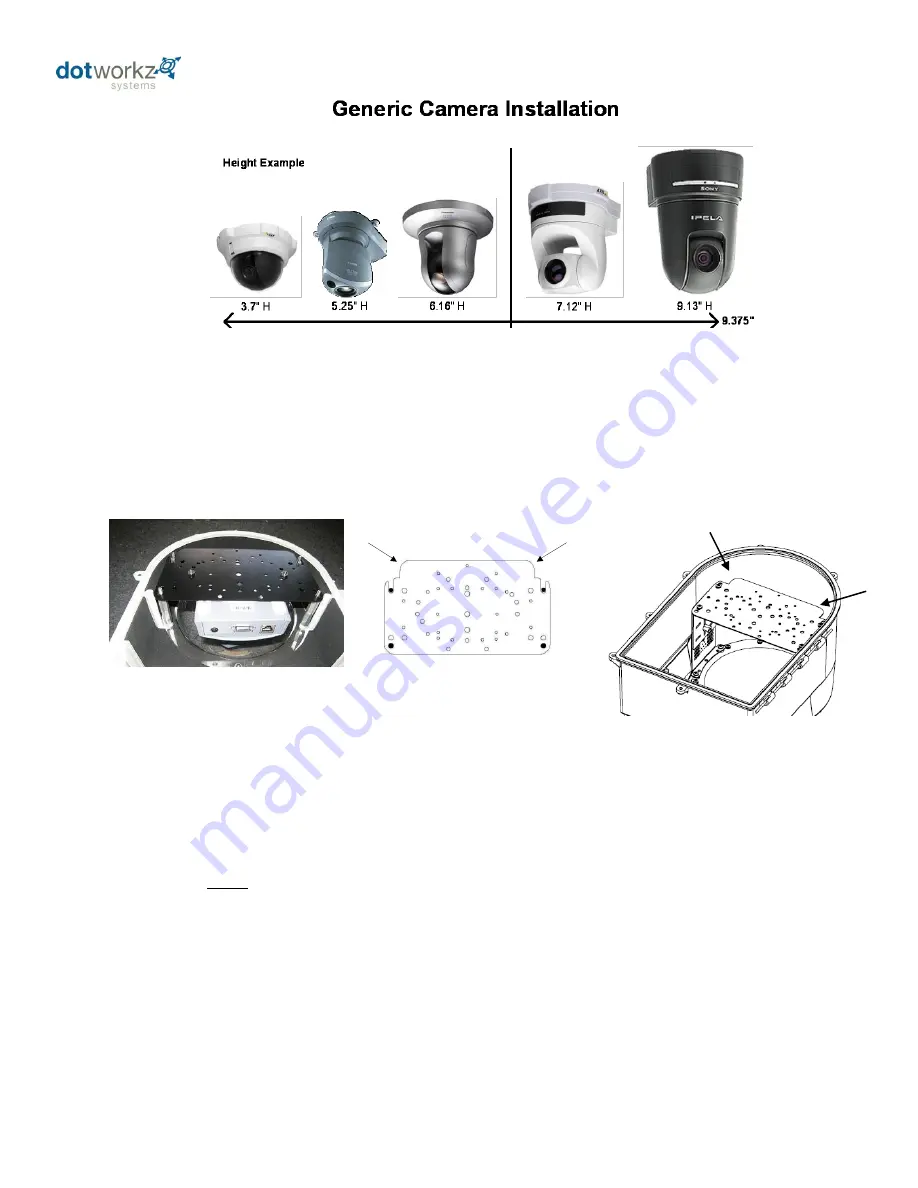
Align camera on D3 camera bracket so as to center camera’s “pan” axis directly over center of camera plate 

provided.  The D3 camera bracket has been pre-drilled with most of the popular camera mounting hole patterns.  Align 
pre-drilled holes on camera plate to best fit your camera model.  Use hardware provided to secure to D3 camera plate.  
On some camera models, new holes may need to be drilled by installer to secure to D3 camera bracket, or for installer to 
provide misc. hardware to secure camera to provided D3 bracket. 

Orientation of Camera Plate when installed into D3 Enclosure 

Steady Step Camera Height Adjustment Brackets 

Steady Step brackets are the brushed aluminum brackets pre-installed in every D3 enclosure.  Using the Steady 

Step brackets as illustrated in following pages, Camera mounting plate can be adjusted to any height from 0.5” to over 
6” by using ¼” stepping ladder system.  Steady Step camera bracket is an easy to adjust, stable, mounting system that 
adjusts to fit virtually every major PTZ camera on the market.   

By utilizing the

 lower

 mounts around the lens on hinged lower of D3, virtually any PTZ or Mini-Dome Camera can 

be mounted into the enclosure at any level.   By using the included 1/8” tall brass standoff set, the Steady Step system 
can be attain half steps of 1/8” steps for a precision optimized camera height adjustment within dome lens.  

The enclosure lens bubble has 3.5” of internal depth clearance, beyond housing depth, that enables the D3 to 

house cameras of heights from mini-domes, to camera heights of over 12” tall, while providing plenty of room for 
integrated products, with convenient mounting / anchoring inserts in upper of housing. 

The Upper mounts above the camera are freed up to mount accessories by utilizing the lower mounts only for all 

sizes of cameras. 

Secure the camera plate to Steady Step slide bracket by using (4) #8-32 Pan Head 

Machine screws into D3.

This edge nests in arch at front of D3

This edge of the bracket faces back of the D3


Содержание D3 SERIES

Страница 1: ...PRODUCT INSTRUCTIONS D3 SERIES CAMERA ENCLOSURES ...

Страница 2: ...for camera installation Camera Mount Bracket 4 Intro to MVP Power 5 24V Input MVP Power 6 High Voltage Input MVP Power 7 Camera Power Setup Standard 12VDC Connector and NON STANDARD 12VDC CONNECTOR 8 Camera Installation Generic 9 Steady Step Mounting Instructions 10 11 COOLDOME Input Configuration 12 13 Power Specifications High Voltage Inputs 14 D3 Exploded View 15 D3 Mounting Template 16 ...

Страница 3: ...tional Security Industry Organization Furthermore Dotworkz Systems shall have no liability where a schedule is specified for regular replacement maintenance or cleaning of certain parts based on usage that the end user has failed to abide to such schedule attempted repair by non qualified personnel operation of the Product outside of the published environmental and electrical parameters if such Pr...

Страница 4: ...presence of non insulated dangerous voltage within the product s enclosure that may be of sufficient magnitude to constitute a risk of electric shock to persons The exclamation point within an equilateral triangle is intended to alert the user to the presence of important operating and maintenance servicing instructions in the literature accompanying the appliance UNPACKING Unpackcarefully Electro...

Страница 5: ...t to eliminate any moisture dust and insect damage safety performance reliability and maintenance related issues Use of Electrical Conduit without sealing the entry ports inside wire feeds within Camera Enclosure will subject the inside of your enclosure to possibility of condensation driven moisture dust and insect contamination hazards Dotworkz has provided each enclosure with two Cable Gland St...

Страница 6: ...3 ...

Страница 7: ...y Available by special order Axis 231D 232D DVTel 9840 Merit LiLin PIH 7000 7600 7625 PiXORD P 463T Fast Speed Dome Pelco Spectra IV Sony SNCRH124 SNC RS44N SNC RS46N Toshiba IK DP30A Component Check List For D3 Included Standard Hardware for Camera Mounting 20 24V Input Blue Bypass Cable In MVP models only 1 20 ...

Страница 8: ...gh Voltage 110 220 VAC Or Low Volt 24 VAC VDC Or Output Voltage to Power Camera MVP provides step down voltage to supply camera power for 12VDC and 24V Cameras 24V Camera Supply 24V output depends on Site Power Input for either 24V Direct Current or Alternating Current see table above Voltage Matrix for Input Output Optional 24VAC Transformer Module available for 24VAC only cameras to convert 110 ...

Страница 9: ... insert similar Plug on 24V Bypass Cable Tighten screws on plug to secure Locate 24V Bypass Cable in Hardware Pack Provided 24 VDC Connect wires to appropriate Color coded terminal shown above 24 VAC hook up has no polarity 24 VDC Color Code Red Positive Blue Negative When all wiring is complete secure screws from plug to panel mount Then secure all wiring to be sure it does not interfere damage f...

Страница 10: ...ories max MVP using 110 220 VAC input to S Type enclosure Using ONE Output Using BOTH Output Channels 12VDC 24VDC Model 12 VDC Output OR 24 VDC Heater Blower 25 watts or 25 watts 25 watts first channel 5 watts on second Channel Tornado 25 watts or 50 watts 25 watts first channel 25 watts on second channel Ring of Fire 25 watts or 25 watts 25 watts first channel 5 watts on second channel Run 110 22...

Страница 11: ...et Right Angle Standard Inline version If you IP camera s power connector is different but still accepts up to 13VDC for power please see our section on Camera Power Setup NON STANDARD CONNECTOR for instructions on how to power your camera Below are pictures of typical NON STANDARD CONNECTORS DC plugs with NO center pin Terminal pin connectors Terminal connector ...

Страница 12: ... Steady Step camera bracket is an easy to adjust stable mounting system that adjusts to fit virtually every major PTZ camera on the market By utilizing the lower mounts around the lens on hinged lower of D3 virtually any PTZ or Mini Dome Camera can be mounted into the enclosure at any level By using the included 1 8 tall brass standoff set the Steady Step system can be attain half steps of 1 8 ste...

Страница 13: ...ments To adjust 1 8 between step settings add 1 8 brass male male hex stand off ITEM NO 6 shown in detail D below and provided in D3 hardware pack by threading on top of movable slide bracket of steady step bracket system then fastening camera bracket CB 1007 or AB 1007 ...

Страница 14: ...11 ...

Страница 15: ... load it is best to run two pairs individually So each 12VDC paired wiring runs load of one cooler Low Voltage 12 VDC Output Terminals Color Symbol Terminals Description Red V 9 10 11 Positive VDC Black V 12 13 14 Negative VDC 12 VDC Cable to COOLDOME Turn Off Power or leave power disconnected during Installation of All Wiring Follow all local and relevant electrical codes standards Test all Wirin...

Страница 16: ... power and COOLDOME Voltage drop is based on fully loaded cooler engaged conditions and camera powered allowing up to 3 amps at typical ambient temperatures of 100F Inside D3 CD at rear of upper on enclosure will be two pairs of color coded screw terminal blocks to conveniently and securely attach low voltage wiring Always check voltage to assure 12VDC is properly wired into enclosure and observe ...

Страница 17: ...14 D3 High Voltage Power Supply Specifications D3 COOLDOME SP 500 12 Power Supply D3 MVP Models High Voltage Inputs ...

Страница 18: ...15 D3 Exploded Detail ...

Страница 19: ...16 D3 Mounting Detail ...

Отзывы: