background image

X-PLORA 

V8


POWER SUPPLY OPTIONS & WIRING


Issue 3: 19

th

 October 2006


3-component setup, standard power supply 


X-PLORA 

V8


TRIPLE-X  


X-RAY 

V8 


XT-100


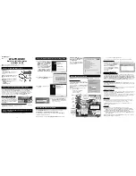
Figure 1 


 The standard 3-component setup using the original 

TRIPLE-X PSU 

(bottom left) is shown in figure 1. 

 
The power connector from the

 X-PLORA

V8

 mates with 

the 4-way socket labelled 

X-PLORA

V8

 on the rear of the 

TRIPLE-X PSU

. The connector should fit comfortably 

with a small click when properly seated.  
 
The power connector from the

 X-RAY

V8

 mates with the 

5-way socket labelled 

X-RAY

V8

 on the rear of the


TRIPLE-X PSU

. The connector should fit comfortably 

with a small click when properly seated. 
   
 The power connector from the

 XT-100

 Integrated 

amplifier


mates with the 6-way socket labelled 

XT-100


on the rear of the

 TRIPLE-X PSU

. The connector should 

fit comfortably with a small click when properly seated. 


3-component setup, upgraded power supply 


X-PLORA

V8

                           TRIPLE-X170    

 X-RAY

V8 


 XT-100


Figure 2 


The upgraded 3-component setup using the 

TRIPLE-

X170 PSU 

(bottom left) is shown in figure 2.  

  
The wiring is identical to that given under the standard 
setup shown above. Simply remove the 

TRIPLE-X PSU


and use the 

TRIPLE-X170 PSU

 in its place.


4-component setup, upgraded power supply 


   X-PLORA

V8 


X-RAY

V8


X-DAC

V8


XT-100


TRIPLE-X170 

Figure 3 


The recommended power supply wiring for the four-
component setup, including upgrade power supply and 

X-DAC

V8

, is shown in figure 3. 

 
The power connector from the

 X-PLORA

V8

 mates with 

the 4-way socket labelled 

X-PLORA

V8

 on the rear of 

the

 X-DAC

V8

. The connector should fit comfortably 

with a small click when properly seated.  
 
 The power connector from the

 X-RAY

V8

 mates with 

the 5-way socket labelled 

X-RAY

V8

 on the rear of the 

X-DAC

V8

.The connector should fit comfortably with a 

small click when properly seated. 
 
   The 

XT-100

 integrated amplifier should be powered 

from the upgrade 

TRIPLE-X170

 power supply unit. 

Connect your 

XT-100

 to this supply through the 6-way 

XLR socket at the back. The

 X-PLORA

V8 

and 

X-

RAY

V8


are now supplied from the 

X-DAC

V8

. This frees 

up reserve supply for the power amplifiers in the 

XT100

.  


This is by no means an exhaustive list, as it is possible 
to use the original TRIPLE-X power supply, say, to 
supply the CD player alone further isolating it from the 
DAC and other circuits. The beauty of this system is its 
incredibly flexible allowing considerable tweaking to 
obtain optimum audio performance.


Page 6


of


14 

Содержание X-PLORA V8

Страница 1: ... sound quality a perfect answer to digital and analogue tuner requirements in a small beautifully engineered package Used properly and carefully it should give many years of outstanding musical reproduction Dust regularly with a soft duster or soft brush but be careful when using cleaning or polishing agents they may harm the surface finish If you have any questions about your audio system Please ...

Страница 2: ...nstallation Aerial Audio connection 6 Facilities and connections Illustrations front and rear panels 7 Remote control Operation and illustration 8 9 DAB button functions Band auto tune manual tune presets info menu 10 FM function buttons Auto tune band manual tune presets mono stereo info menu 11 Tuner problems Basic tuner fault finding 12 Tuner specifications 13 Manual history Page 2 of 14 ...

Страница 3: ...rm your dealer who should then check the unit before further use Entry of liquid into the X PLORA V8 is dangerous and may cause electric shock or fire hazard Do not place the unit near direct heat sources such as radiators direct sunlight or other equipment Do not remove any covers or try to gain access to the inside There are no internal adjustments or fuses you can replace yourself Refer all ser...

Страница 4: ...dell appare FACHGERECHTE ENTSORGUNG Das auf der Geräterückseite angebrachte Label deutet dass das Produkt nicht mit konventionellem Hauskehricht entsorgt werden darf Um Schäden und Verschmutzungen an Umwelt und Mensch zu vermeiden muss das Produkt fachgerecht entsorgt und von anderem Abfall getrennt werden Wenden Sie sich bei Fragen hierzu an Ihren Fachhändler oder an eine öffentliche Informations...

Страница 5: ...eviews which recon it s probably the best CD player ever INSTALLATION Position the X PLORA V8 on a stable horizontal surface where there is no risk of it being knocked or subjected to vibration such as from loudspeakers AERIAL ANTENNA For ease of installation a tri band aerial is supplied with the unit This covers the FM DAB II III and L bands and picks up sufficient signal for most domestic purpo...

Страница 6: ...ve Simply remove the TRIPLE X PSU and use the TRIPLE X170 PSU in its place 4 component setup upgraded power supply X PLORAV8 X RAYV8 X DACV8 XT 100 TRIPLE X170 Figure 3 The recommended power supply wiring for the four component setup including upgrade power supply and X DACV8 is shown in figure 3 The power connector from the X PLORAV8 mates with the 4 way socket labelled X PLORAV8 on the rear of t...

Страница 7: ...NEL 1 2 3 1 BAND SEARCH buttons and IR lens 2 DISPLAY window 3 TUNE UP DOWN SEARCH buttons REAR PANEL 4 5 6 7 4 DIGITAL OUTPUTS RCA coaxial and optical 5 LEFT AND RIGHT RCA Phono outputs 6 DAB FM aerial F TYPE 7 POWER CABLE for connection to Triple X psu only Page 7 of 14 ...

Страница 8: ...eaker FM stations DAC Buttons DIG 1 Selects DAC digital input 1 DIG 2 Selects DAC digital input 2 DIG 3 Selects DAC digital input 3 USB Selects DAC USB input Amplifier Buttons PHONO Selects Phono input AUX 1 Select Source AUX1 or PDI AUX 2 Select source AUX 2 AUX 3 Select source AUX 3 CD Buttons TIME Displays Track Time Time remaining 0 9 Buttons Used to select track numbers CHECK Check pre progra...

Страница 9: ...dcast being listened to if applicable TUNE UP DOWN To select a station simply press the TUNE or buttons to cycle through the list of receivable broadcasts in your area When the required station is displayed press the SELECT button to listen See the section on the PRESET buttons to store favourite stations for easy recall PRESET UP and PRESET DOWN remote control PRESET UP DOWN buttons are used to s...

Страница 10: ... options and the SELECT button to choose displayed option Menu options available for DAB are Manual Tune Allows manual search of ensembles and DAB frequencies Canadian L band Enables Canadian L Band European L Band Enables European L band Service Base Factory use only Customer Version Software version reference System reset RESETS all presets and performs a new scan of DAB band Page 10 of 14 ...

Страница 11: ...ired Press PRESET UP DOWN buttons until the desired preset is displayed Press and hold STORE to accept this preset The display will indicate the preset has saved and then revert to selected station Note this will overwrite any station stored previously on this preset Briefly pressing the button will display current preset without storing There are 10 presets available for programmes on the FM band...

Страница 12: ...ition aerial Consider a rooftop DAB FM aerial page 5 AERIAL ANTENNA Tuned station does not transmit the RDS feature RDS information feature therefore unavailable Tuner does not display FM RDS station name and or text Local signal insufficient to receive RDS properly Try repositioning the whip aerial if used Improve the aerial Remote control does not work One or more batteries fitted the wrong way ...

Страница 13: ...1 KHz THD 0 5 90MHz 200mV 75KHz Dev Fmod 1 KHz Stereo Channel Separation 30 dB RDS data CENELEC EN50067 compliant WHIP AERIAL Operating Frequency FM Band 88 108MHz Band III 174 240MHz L Band 1452 1492MHz Gain FM Band III 2dBi L Band 5dBi Impedance 75Ω S W R 2 0 1 at res freq Polarization Vertical Connector F type Operating temperature 20 to 65 C Storage temperature 30 to 75 C Length Sleeve 36mm Re...

Страница 14: ...8 MANUAL REVISION Issue 3 19th October 2006 RELEASE DATE CHANGES Issue 1 6th September 2006 1st release Issue 2 18th Ocober 2006 Added power supply wiring options Issue 3 19th October Improved P 7 Page 14 of 14 ...

Отзывы: