Страница 1: ...formation Is Included with this unit This Information Includes the INSTRUCTION BOOKS the REPLACEMENT PARTS and the WARRANTIES This Information must be Included to make sure state laws and other laws a...
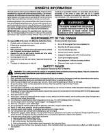
Страница 2: ...s and conditions noted inthis Limited Warranty we shall at our option repair or replace at no cost to the original purchaser any part covered by this Limited Warranty during the applicable warranty pe...
Страница 3: ...observe the following safety instructions could result in serious injury or death I General operation 1 Read understand and follow allinstructions inthe InstructionBook on the machine the engine and w...
Страница 4: ...fall off and be seriously injured or interfere with the safe operation of the machine 5 Never allow children to operate the machine Instruct children in the potential dangers of the machine 6 Use extr...
Страница 5: ...erson dde with you on the unit or on any accessories A passenger will make the unit harder to control block the visibility or distract the operator and is dangerous to the operator the passenger and t...
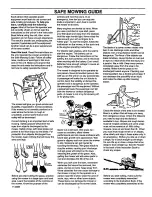
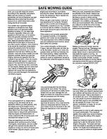
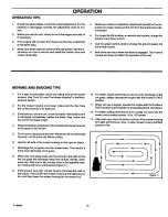
Страница 6: ...not operated correctly or not regularly serviced the mower can be dangerous The most important rule to follow is always use good judgement and common sense Mow safely and carefully Your mower will ea...
Страница 7: ...r empty the grass bagger always stop the engine Before each use of the grass bagger check for cracks wear or deterioration Before you use the grass bagger replace a damaged part with a replacement par...
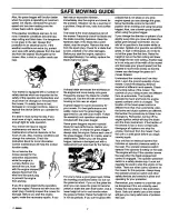
Страница 8: ...hout stopping the engine Disconnect the spark plug wira On or near roads watch out for traffic Direct discharge away from roads When mowing avoid areas where traction is unsure Look back before changi...
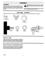
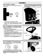
Страница 9: ...low The fasteners are shown full size The quantity is shown in brackets 2x82 2 CarriageBolt 9416O 2 Knob 14x79 2 Wing Nut 17x47Z 2 Washer 31xll 2 LockingRing 17x91Z lO Washer 1 Keys Ring CHECK THE TIR...
Страница 10: ...nt forward 2 Look at the hub of the steering wheel Make sure the locking clip is in place Inside the hub 3 Slide the cover over the steering post Figure 2 4 Slide the steering wheel onto the steering...
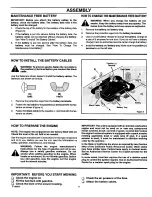
Страница 11: ...e to the negative terminalwith the fas teners as shown I B Black Cable PosilJve Term nal A Battery Tray I Figure4 HOW TO PREPARE THE ENGINE NOTE The engine was shipped from the factory filled with oil...
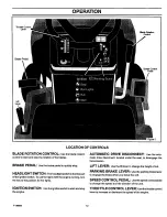
Страница 12: ...m the key to the position for the lights IGNITION SWITCH Usetheignitionswitchtostartandstop the engine AUTOMATIC DRIVE DISCONNECT usetheauto matic drive disconnect located under the seat to disengage...
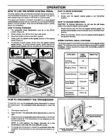
Страница 13: ...n using a grass bagger move the throttle control to the FAST position For maximum charging of the battery and for a cooler running engine and transmission operate the en gine in the FAST position 2 3...
Страница 14: ...our foot from the speed control pedal The speed control pedal will automatically returnto the NEUTRAL position 2 When the unit stops slowly move the speed control pedal to the desired direction SPEED...
Страница 15: ...e mowerhousingand backto raisethe mowerhousing Figure10 2 When yourideona sidewalkorroad movethe liftleverto the highestpositionand move the blade rotationcontrolto the DISENGAGE position LiftLever HO...
Страница 16: ...control of the unit always select a safe speed HOW TO OPERATE THE UNIT ON HILLS A WARNING Do not ride up or down slopes that are too 2 steep to back straight up Never ride the unit across a slope See...
Страница 17: ...d shorten the life of the valves Full Fuel Tank CARBURETOR The factory settings for the carburetor are for most conditions Ifthe engine Is operated under the following conditions you can adjust the ca...
Страница 18: ...lade is bent or damaged immediately replace the blade Also make sure the nut for the blade is tight Keepthe blade s sharpened Wornbladeswillcausetheends of the grassto turnbrown 5 6 7 8 9 Do not cut o...
Страница 19: ...lows How To Remove The Mulcher Plate 1 Raise the deflector Remove the two wingnuts B and two car riage bolts A Figure t2 2 Liftthe mulcher plate away from the mower housing 3 Attach wingnuts B and car...
Страница 20: ...Before you make an Inspection adjust A ment or repair to the unit disconnect the wire to the spark plug Remove the wire from the spark plug to prevent the engine from starting by accident NOTE Torque...
Страница 21: ...ccident 8 Fasten the blade with the originalwashers and nut Make sure the outside rim of the Belleville washer is against the blade Figure 14 A WARNING Always keep the nut tight that holds the blade A...
Страница 22: ...re 16 4 Checkthe blade s Keep a sharp edge on the blade s Ablade that is not sharp will cause the tips of the grass to become brown A ARNING If the brake pads do not press tightly against the pulleys...
Страница 23: ...pulling a heavy load or 3 the unit will not move forward Adjust the belt as follows 7 Ifthe belt still slips after the belt has been adjusted then the motion drive belt is worn or damaged and must be...
Страница 24: ...uric acid which is harmful to the skin eyes and clothing If the acid gets on the body or clothing wash with water 1 Disconnect the black cable from the negative terminal Figure 22 2 Disconnect the red...
Страница 25: ...ou replace the fuel filter or the fuel line the fuel tank must be empty If the fuel filter is dirty the engine will run rough and have less performance Remove the old filter Figure 24 Replace the old...
Страница 26: ...e mower drive belt is against the eta ek pulley Also make sure the mower drive belt is not twisted 3 Attach the front hanger to the axle support with the hanger rod Fasten with the fasteners as shown...
Страница 27: ...L ADJUSTMENT position Figure 27 _lb WARNING The lift lever is spring loaded Make sure the lift lever is locked in the LEVEL ADJUSTMENT position 6 Loosen the left and right adjuster knobs Figure 28 Pus...
Страница 28: ...ion drive belt is on the left side of the steering shaft assembly 3 Installthe end ofthe motion drive belt around the drive pulley Figure 30 4 Put the motion drive belt around the V idler pulley Insta...
Страница 29: ...r drive belt Pull the belt retainer away from the right mandrel pulley Put the belt around the right mandrel pulley 6 Pull the belt retainer away from the left mandrel pulley Put the belt around the l...
Страница 30: ...de rotation control to the DISENGAGE position 4 Again clean the top of the mower housing 5 After you cut the grass clean the bottom oftha mower housing STORAGE over 30 days At the end of each year pre...
Страница 31: ...g 2 Clean the air filter 3 Adjust the carburetor 4 Adjust the throttle control 5 Drain the fuel tank Clean the fuel line Replace the fuel filter PROBLEM A hot engine causes a decrease in power 1 Clean...
Страница 32: ...degrees If the riding mower Is used with a pull behind or rear mounted attachment do not operate the unit on a slope that is greater than 10 degrees A 15 degree slope Is a hill that Increases In heigh...
Страница 33: ...NOTES F 98889 33...
Страница 34: ...NOTES F 98889 34...
Страница 35: ...3 Drive Brake 23 Filter Fuel 25 Fuse 30 Headlight 30 Lubrication 25 Mower Housing Clean 30 Install 26 Level 27 Remove 26 Muffler 20 Speed Control Pedal 24 Storage 30 Maintenance Chart 20 Motion Drive...
Страница 36: ...Model No 24762 9 Bushel Capacity For 42 and 46 38 MULCHER KIT Model No 24750 40 MULCHER KIT Model No 24755 42 MULCHER KIT Model No 24758 F 98889 TIRE CHAINS Model No 24530 For 18x8 5 inchtire Model N...