


How to access the P-numbers
1.
Turn the power ON, but
DO NOT ALLOW EQUIPMENT TO OPERATE
.
2.
Press the
▼
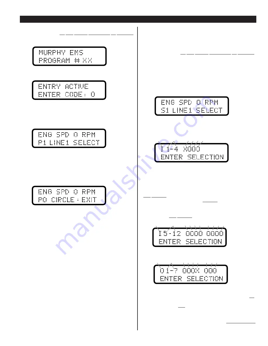
button until the title page appears:
3.
Press the
●
button until the entry code screen appears:
4.
Press the
▼
or
▲
buttons until appropriate entry code is displayed.
(See separate document which shows the entry/access codes for your unit.)
5.
Press the
●
button once, the P-numbers main menu will be displayed.
The display window will show the P-1 screen, for example:
6.
Now that you are in the P-numbers, you can go to a specific function by
pressing the
▲
or
▼
buttons then pressing the
●
button to enter the specific
function. Now you can increase, toggle, or decrease that setpoint.
Once you have finished adjusting or viewing the desired P-numbers, you can exit
the set-up mode by holding the
▼
button until the Exit Screen is displayed:
Now press the
●
button to set the EMS back into normal operation and scrolling
mode (automatic or manual as applicable). If you forget to exit the
P-numbers menu, the EMS will exit for you after a 5 minute delay.
Acknowledging Service Reminders
To acknowledge a service reminder, you must first perform the required service
to your equipment, then, clear the reminder message by accessing the P-numbers.
1.
Press the
▼
button until the title page appears:
2.
Press the
●
button until the entry code screen appears:
3.
Press the
▼
or
▲
buttons until appropriate entry code is displayed.
4.
Press the
●
button once, the P-numbers main menu will be displayed.
5.
Next, using the
▼
or
▲
buttons, scroll to the P-number which represents the
service performed. Press
●
button to enter the function and toggle the NO to
YES, using the
▲
button.
If you wish to change any service reminder interval, you may have to do so in
the S-numbers (refer to “Section 2” of these installation instructions, separate
document, or the detailed sequence of operations provided with custom
programmed unit).
6.
Now, exit to the main displays.
Inputs and Outputs Signal Checking
Before attempting to start your system, check which inputs and outputs are active
and properly wired. The diagnostic information for confirming your EMS
input/output setup can be found under the S-numbers menu or the Main Displays.
To access the input/output diagnostic information do the following:
1.
Turn the power ON, but
DO NOT ALLOW EQUIPMENT TO OPERATE
.
2.
Press
▲
to see if I/O is in main displays. If not found here, press
▼
until
tittle page appears.
3.
Press
●
until the entry code screen appears.
4.
Press
▼
or
▲
until appropriate entry code for S-numbers is displayed.
(See separate document which shows the entry/access codes for your unit.)
5.
Press the
●
button once, the S-numbers main menu will be displayed.
The display window will show the S-1 screen, for example:
6.
Press the
●
button to access this specific sub-menu.
7.
Press the
▲
or
▼
buttons until you see the following screen.
The Letter “I”, shown in the upper most-left corner, determines that the screen
displayed shows the EMS inputs.
Next to the “I” are the numbers 1-4 which represent the 3 standard digital inputs,
and the additional input (depending on the program configuration).
When the letter “O” is displayed next to input numbers, that means the controller
is NOT SENSING an input signal. The above example shows input 1 has tripped,
for example vibration. Inputs 2, 3 and 4 are not sensed. By resetting the vibration
switch, Input 1 will display “O”.
The next screen will show the balance of the inputs. The example below shows
that the controller is NOT SENSING input signals 5 - 12:
Press the
▲
button to bring up the outputs display:
The above example shows Output number 4, designated with an “X”. This means
that the controller software is calling for that output signal the be turned ON.
A “O” displayed means that the controller software is calling for the designated
output signals to be turned OFF.
Refer to the “Pin Color Code and Terminal Designation Chart” (program specific
document) and double check the wiring diagram(s) provided with your unit.
To exit S-numbers menu, press and hold the
▼
button until
S0 CIRCLE=EXIT
screen appears. Now exit to the main displays.
EMS-94072N page 5 of 8
INSTALLATION AND SET-UP
continued
I
=Inputs
1
1 to 4
2 3 4
I
=Inputs
5
5 to 12
6 7 8
9 10 11 12
O
=Outputs
1
1 to 7
p
2 3 4
5 6 7
Note:
These are the analog
inputs that may be used as
digital inputs. Depending on
the analog signal, an X or an
O may be present.


