©2010-2015 by Murata Electronics N.A., Inc.
WIT910 Integration guide (R) 05/14/15
www.murata.com
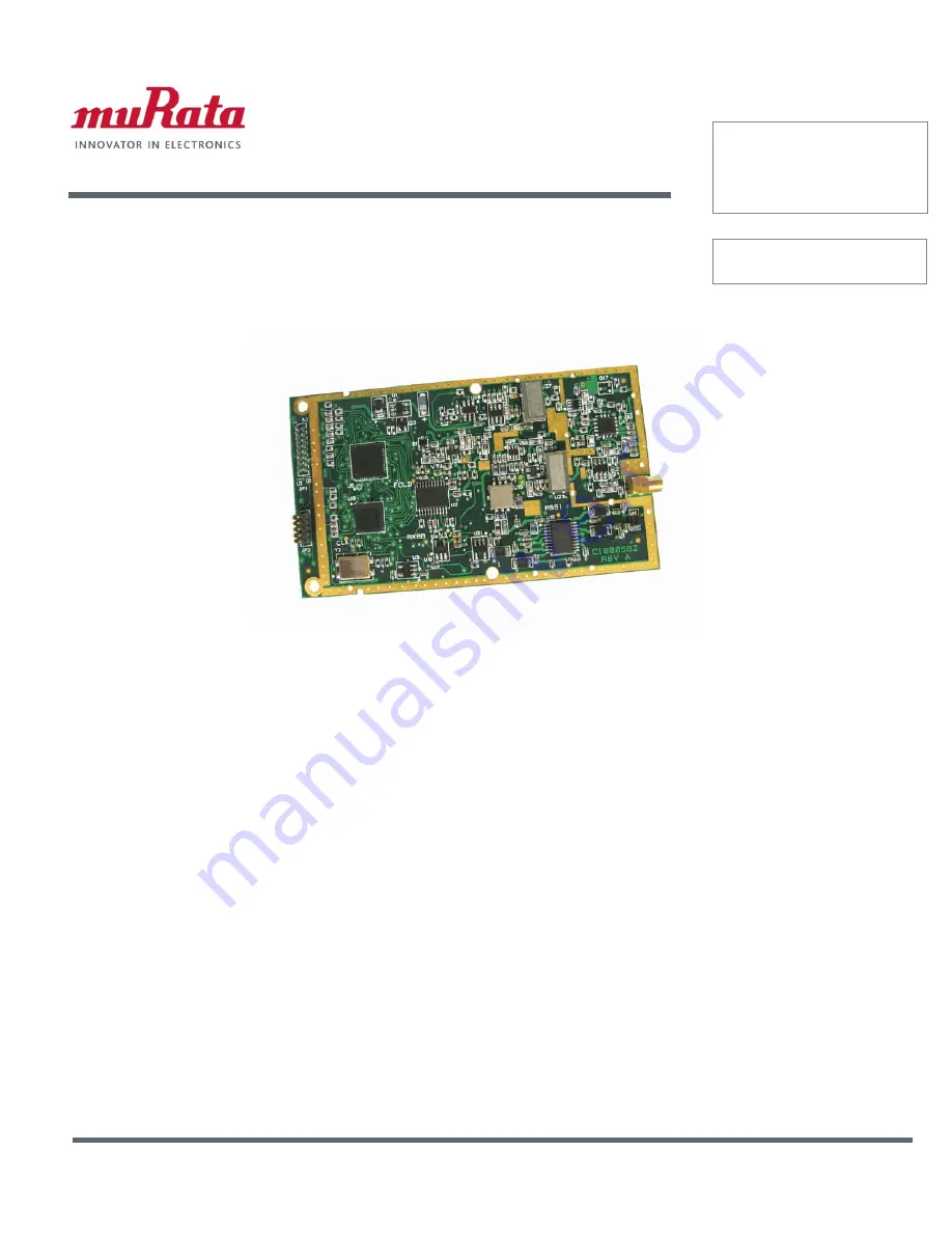
WIT
9
10
900 M
Hz
Spread Spectrum
Wireless Industrial
Transceiver
Integration
*XLGH
Страница 1: ...2010 2015 by Murata Electronics N A Inc WIT910 Integration guide R 05 14 15 www murata com WIT910 900 MHz Spread Spectrum Wireless Industrial Transceiver Integration XLGH...
Страница 2: ...ng the same information Any other mode of operation using this antenna is forbidden Notice to WIT910 users installers using the following fixed antennas Cushcraft 8 5 dBi Yagi The field strength radia...
Страница 3: ...w Control Mode 11 3 PROTOCOL MODES 12 3 1 1 Data Packet 14 3 1 3 Connect Packet 15 3 1 4 Disconnect Packet base only receive only 15 4 MODEM INTERFACE 16 4 1 Interfacing to 5 Volt Systems 17 4 2 Evalu...
Страница 4: ...n 44 8 1 2 Power Specifications 44 8 1 3 RF Specifications 44 8 1 4 Mechanical Specifications 44 8 2 Serial Connector Pinouts 45 8 3 Approved Antennas 45 8 4 Technical Support 46 8 5 Reference Design...
Страница 5: ...uces possibility of eavesdropping Nonvolatile memory stores configuration when powered off Smart power management features for low current consumption Dynamic TDMA slot assignment that maximizes throu...
Страница 6: ...and frequency hopping FH either of which can generally be adapted to a given application Direct sequence spread spectrum is produced by multiplying the transmitted data stream by a much faster noise l...
Страница 7: ...vantage in that as the transmitter cycles through the hopping pattern it is nearly certain to visit a few blocked channels where no data can be sent If these channels are the same from trip to trip th...
Страница 8: ...ch transmissions will be received and not discarded Registration also allows tracking of remotes entering and leaving the network The base station builds a table of serial numbers of registered remote...
Страница 9: ...iguration all communications take place between the base station and any one of the remotes Remotes cannot communicate directly with each other It should be noted that point to point mode is a subset...
Страница 10: ...tween transmissions intended for it and transmissions intended for other remote devices This is necessary to identify the remote to which the base station should send data When the user packet is rece...
Страница 11: ...ride this handle mechanism and always assign the remote the same handle 2 2 4 TDMA Operation For applications needing guaranteed bandwidth availability the TDMA operation of the WIT910 can meet this r...
Страница 12: ...rmine that the base slot requires approximately 32 8 172 8kbps 7 04 ms 8 52 ms Each remote time slot will be 25 ms 8 52 ms 5 1 11 ms 2 18 ms 5 From our RF data rate of 172 8kbps we see that it takes 4...
Страница 13: ...sequence spreading this would imply a loss of contact on average of over 30 seconds per hour per station The WIT910 overcomes this problem by hopping rapidly throughout the band in a pseudo random pa...
Страница 14: ...e command z or assert and de assert the Sleep pin There are three modes for the escape sequence controlled by the Set Escape Sequence Mode command zc zc 0 Escape sequence disabled zc 1 Escape sequence...
Страница 15: ...s host might really be 57 601 and at the receiving radio s host it might be 56 599 This is similar to a situation where the transmitting radio is sent data at a higher baud rate than the baud rate at...
Страница 16: ...sure that a packet is transmitted to the base without being broken up over multiple hops The data length value in the data packet becomes the effective minimum packet length and maximum packet length...
Страница 17: ...re sent to the user application at the base station and at the remote No sequence numbers are provided packet types supported Data CONNECT DISCONNECT modes 03 08 reserved for future use mode 09 This m...
Страница 18: ...r than that will be discarded and not sent See Get Maximum Data Length for more details 3 1 1 Data Packet Modes 01 02 Base 1110 1001 00HH HHHH LLLL LLLL 0 208 bytes data Remote 1110 1001 0000 0000 LLL...
Страница 19: ...assigns the remote a handle value may or may not assign it a dedicated time slice depending on the user settings and notifies the user application of the new remote with a connect packet The network n...
Страница 20: ...the user on or off In normal operation this signal should be asserted When negated the WIT2450 buffers receive data until RTS is asserted 0v 1 Receive data RxD enabled 3 3v 0 Receive data RxD disabled...
Страница 21: ...nterfaced to an RS 232 transceiver RTS and DTR need to be pulled high on the transceiver side In the evaluation unit RTS and DTR are pulled high on the transceiver side so the evaluation unit will wor...
Страница 22: ...er to Section 2 2 3 TDMA Mode for the remote throughput calculation 4 4 Power On Reset Requirements The WIT910 has an internal reset circuit that generates and maintains the WIT910 in a reset state un...
Страница 23: ...H when using the wr command in Section 5 2 Network Commands If for any reason an RF channel is missed the RSSI line will dip and then recover to the correct level This recovery period is around 30ms H...
Страница 24: ...ach modem command must be followed by either a carriage return or a line feed 5 1 Serial Commands These commands affect the serial interface between the modem and the host The default settings are 960...
Страница 25: ...ode Enables the base station to operate in a multipoint network Depending on the user application more or less acknowledgment may be desired by the application Remotes can operate in transparent mode...
Страница 26: ...mit Power 0 10mW 1 100mW default 2 500mW wr Read Receive Signal Strength wu 0 1 Set Point to Point Direct Mode 0 Multipoint mode default 1 Point to point direct mode Set Transceiver Mode Sets modem op...
Страница 27: ...Power The WIT910 has three preset transmit power levels 10mW 10dBm 100mW 20dBm and 500mW 27dBm Control of the transmit power is provided through this command Default is 100mW Read Receive Signal Stren...
Страница 28: ...8H default 32 bytes px 0 1 Set ARQ mode 0 ARQ enabled default 1 ARQ disabled redundant transmission Note Incorrect setting of these parameters may result in reduced throughput or loss of data packets...
Страница 29: ...o useful to assure a minimum remote throughput Set Packet Attempts Limit If ARQ Mode is set to 0 sets the number of times the radio will attempt to send an unsuccessful transmission before discarding...
Страница 30: ...sion on each hop for the base station time slot in 4 byte increments Maximum value is 2FH which corresponds to 188 bytes If using a protocol mode attempting to send a packet with a length longer than...
Страница 31: ...quence only works immediately after reset this is the default When set to 2 the escape sequence may be used at any time in the data stream when preceded by a pause of 20 ms For backwards compatibility...
Страница 32: ...and afterwards if you wish the factory default settings to be remembered the next time you cycle power or reset the radio Recall Memory Useful for restoring the power on settings after experimenting w...
Страница 33: ...lay remote only pv 0 1 Set Slot Assignment Mode base only pw 00 2f Set Base Slot Size base only px 0 1 Set ARQ Mode Status Commands zb 0 1 Banner Display Disable zc 0 2 Set Escape Sequence Mode zh Rea...
Страница 34: ...eloper s kit is shipped from the factory one HN 591 is set up as a base station and the other is set up as a remote The interface rate for both modems is set at 9600 bps The default setting for the ne...
Страница 35: ...and Software CD included in the developer s kit Install WinCOM by navigating to the Software Tools directory on the Manuals and Software CD and double click on wincom2 1 exe follow the installation wi...
Страница 36: ...ows functionality in typical fashion The Options menu contains the selections Show Comm Errors which lists any errors encountered in the PC UART Check Comm Ports on Bootup tells WinCom to verify each...
Страница 37: ...play Disable command zb0 The COM port and baud rate can be changed using the drop down menus on the bottom right All the available COM ports will be listed in the menu but will have OK or N A designat...
Страница 38: ...save the parameters m is issued the new parameters will only be valid until power is cycled or DTR is toggled by pressing the F1 key twice New parameter values that have been issued are saved to non v...
Страница 39: ...sor to the left side of the window but the character corresponding to 0xd value of the carriage return will be displayed Similarly if the Hex Mode box is checked all characters are displayed in hexade...
Страница 40: ...m to another WIT2450 this allows you to see what you are typing F6 Toggles stream mode Causes WinCOM to transmit a repeating pattern of characters Useful for testing F8 Toggles binary mode Displays ex...
Страница 41: ...e is no need to click Stop Clicking on the Transmit button a second time will have the string transmitted a second time The third allows for checking of available Comm Ports and is useful for refreshi...
Страница 42: ...in the Data to Transmit window In the bottom window you will see the entire packet being built as the data is entered in the windows When all the data has been entered click on the Transmit button to...
Страница 43: ...its 200 milliseconds asserts DTR waits 200 milliseconds sends the configuration mode escape sequence waits 200 milliseconds and then sends the m command to the radio What this script file does is set...
Страница 44: ...ays with a bar showing loading progression Once the file has finished transmitting the Final Average Throughput and Bytes sent numbers will be displayed Finally the eighth tool is Save to File which l...
Страница 45: ...rol mode for each unit To access modem control mode use the F1 key to toggle DTR to 0 and back to 1 and then press the F3 key which sends the wit2400 escape sequence If you are not using COM24 simply...
Страница 46: ...g data check that the base s default handle is the same as the remote s In a multipoint application check that the remote is not configured for protocol mode and that the base is using the correct pro...
Страница 47: ...stream The nature of the packetized RF channel imposes a degree of unpredictability in the end to end transmission delay Cannot communicate with the OEM module Make sure DTR and RTS are asserted DSR s...
Страница 48: ...Power 27 dBm Line of site Range 20 miles with omni antenna Frequency Range 902 to 927 MHz Number of Channels 54 US Receiver Sensitivity 103dBm Channel Data Rate 172 8Kbps IF Adjacent Channel Rejectio...
Страница 49: ...vice whenever the WIT910 asserts carrier When connecting to the WIT910 make sure that all of the inputs TXD CFG RTS and SLEEP are terminated for proper operation 8 3 Approved Antennas The WIT910 is de...
Страница 50: ...nical Support For technical support call Murata at 678 684 2004 between the hours of 8 30AM and 5 30PM Eastern Time 2010 2015 by Murata Electronics N A Inc WIT910 Integration guide R 05 14 15 46 of 49...
Страница 51: ...4300 WIT910 8 5 Reference Design 2200 2010 2015 by Murata Electronics N A Inc WIT910 Integration guide R 05 14 15 47 of 49 www murata com...
Страница 52: ...WIT910 8 6 Mechanical Drawing WIT910 2010 2015 by Murata Electronics N A Inc WIT910 Integration guide R 05 14 15 48 of 49 www murata com...
Страница 53: ...on shall be brought against Seller more than twelve 12 months after the related cause of action has occurred Buyer has not relied and shall not rely on any oral representation regarding the goods sold...
Страница 54: ...Mouser Electronics Authorized Distributor Click to View Pricing Inventory Delivery Lifecycle Information Murata OMNI092...