ENC-03J type
7
10. Application
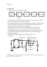
A simplified block diagram is shown in the illustration.
Micro processor
A/D converter
GYROSTAR
ENC-05E
Band pass
filter
Amplifier
High-pass,
Low-pass
1) Positive v) and negative voltage(-) are obtained in the clockwise and counterclockwise
directions, respectively, with the static output as a reference.
2) Cut DC level of output using HPF (Hi-Pass-Filter) with low cut-off frequency on sensor output In
order to cancel bias drift. Cut-off frequency of HPF will affect measurement accuracy. Please
choose a proper cut-off frequency according to the application.
3) Always use an A/D converter of 8 bits or more. Resolution of A/D converter will affect
measurement accuracy . Please choose a proper resolution according to the application.
4) The sampling frequency used for measurement should be 50 times/sec minimum. Sampling
frequency will affect measurement accuracy . Please choose a proper sampling frequency
according to the application.
5) Please choose a proper amplification factor according to the application.
6) Typical circuit
NJM2115 or equivalent
NEW JAPAN RADIO CO., LTD.
ENC-03J
3V
Vcc
1
Out
GND
Vref
4. 7µF
100k
10k
4.7µF
90k
1800pF
V
High-pass filter
Low-pass filter
2
3
4
The high-pass filter’s cut-off frequency in this circuit is approx. 0.3Hz. The low-pass filter’s cut-off
frequency in this circuit is approx. 1kHz.


