
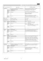
7 Operational Life
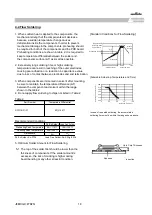
The measured and observed characteristics should satisfy the
Apply 150% of the rated voltage for 1000±12 hours at 125±3
℃
.
specifications in the following table.
Set for 24±2 hours at room temperature, then measure.
Appearance
No marking defects
The charge/discharge current is less than 50mA.
Capacitance
C7: Within ±12.5%
Change
・
Initial measurement for high dielectric constant type
Dissipation
C7: 0.2max
Perform a heat treatment at 150+0/-10
℃
for one hour and then set
Factor
for 24±2 hours at room temperature.
Perform the initial measurement.
・
Measurement after test for high dielectric constant type
Insulation
5
Ω
・
F min.
Perform a heat treatment at 150+0/–10°C for one hour and then let
Resistance
sit for 24±2 hours at room temperature, then measure.
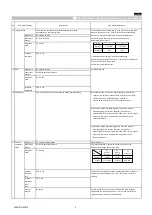
8 External Visual
No defects or abnormalities
Visual inspection
9 Phisical Dimension
Within the specified dimensions
Using calipers
10 Resistance to Appearance
No marking defects
Per MIL-STD-202 Method 215
Solvents
Capacitance
Within the specified tolerance
Solvent 1 :
1 part (by volume) of isopropyl alcohol
Change
3 parts (by volume) of mineral spirits
Dissipation
C7: 0.1max
Solvent 2 : Terpene defluxer
Factor
Solvent 3 : 42 parts (by volume) of water
1part (by volume) of propylene glycol monomethylether
1 part (by volume) of monoethanolomine
Insulation
50
Ω
・
Fmin.
Resistance
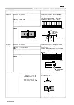
11 Mechanical
Appearance
No marking defects
Three shocks in each direction should be applied along 3 mutually
Shock
Capacitance
Within the specified tolerance
perpendicular axes of the test specimen (18 shocks).
Change
The specified test pulse should be Half-sine and should have a
Dissipation
C7: 0.1max
duration :0.5ms, peak value:1500g and velocity change: 4.7m/s.
Factor
Insulation
50
Ω
・
F min.
Resistance
12 Vibration
Appearance
No defects or abnormalities
Solder the capacitor to the test jig (glass epoxy board) in the same
Capacitance
Within the specified tolerance
manner and under the same conditions as (19). The capacitor
Change
should be subjected to a simple harmonic motion having a total
Dissipation
C7: 0.1max
amplitude of 1.5mm, the frequency being varied uniformly between
Factor
the approximate limits of 10 and 2000Hz. The frequency range, from
10 to 2000Hz and return to 10Hz, should be traversed in
approximately 20 minutes. This motion should be applied for 12
Insulation
50
Ω
・
F min.
items in each 3 mutually perpendicular directions (total of 36 times).
Resistance
13 Resistance to
The measured and observed characteristics should satisfy the
Immerse the capacitor in a eutectic solder solution at 260
±
5
℃
for
Soldering Heat
specifications in the following table.
10
±
1 seconds. Set at room temperature for 24
±
2 hours, then
Appearance
No marking defects
measure.
Capacitance
C7: Within ±15%
Change
・
Initial measurement for high dielectric constant type
Dissipation
C7: 0.1max
Perform a heat treatment at 150+0/-10
℃
for one hour and then set
Factor
for 24
±
2 hours at room temperature.
Perform the initial measurement.
Insulation
50
Ω
・
F min.
Resistance
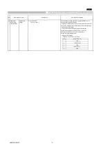
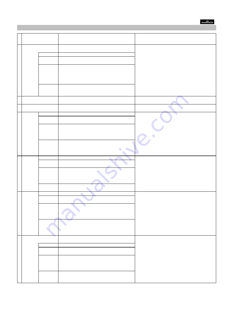
■
AEC-Q200 Murata Standard Specification and Test Methods
No
AEC-Q200 Test Item
AEC-Q200 Test Method
Specification.
JEMCGS-02374
3


