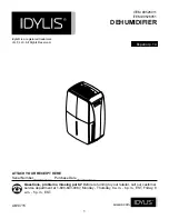
Dehumidifier ML420-MLT1400
8.3 Fault tracing list
The control panel LED are the primary source of information for fault tracing when the unit has given an
alarm and stopped automatically.
Go through the fault tracing list below before contacting Munters service department. The list contains
information for identifying faults that are easy to repair without the help of a technician.
If the unit is equipped with the humidity regulation system RH98, see also appendix
.
Symptom
Indicators
Possible cause
Corrective action
Power supply failure.
Check power supply to the unit.
Mains supply switch (no.1) is set to
”0”.
Set the mains supply switch to ”1” and check that the mains
connection indicator (no. 14) is on.
Transformer TC25 fuse FU26
failure.
Investigate the cause of the fault and rectify. Replace the fuse.
Unit has
stopped.
No lights.
Circuit breaker QM25 tripped due
to a wiring fault.
Investigate the cause of the fault, and rectify.
Reset QM25. If the fault re-occurs, contact Munters.
The unit has been set to
AUTomatic mode by mistake with
no humidity sensor connected.
Set the mode switch to
MAN
ual, and check that the unit starts.
Unit has
stopped.
No. 12
does not
flash.
Humidity sensor fault (AUTomatic
mode).
Set the mode switch to
MAN
ual, and check that the unit starts. If the
unit starts, the fault is probably in the humidity sensor.
Set the mode switch to
AUT
omatic mode, and check the humidity
sensor by seeing if the dehumidifier starts when the humidity sensor
setpoint is reduced. Then reset the humidity sensor setpoint.
Calibrate the humidity sensor (according to the manufacturer's
recommendations) if necessary, or replace it.
Unit has
stopped.
No. 12, 6
and 7 are
flashing.
If both indicators are flashing,
it indicates that one (or both) of
the high temperature cut-outs
(BT27 and BT30) have tripped,
due to either an obstruction in the
reactivation airflow, or because the
reactivation airflow has been set
too low.
Switch off the mains supply and allow the unit to cool down.
Reset QM12 and QM14 circuit breakers as required.
Check that the air inlet, outlet ducts and filters are free from
obstructions and are not blocked with dirt.
Switch on the mains supply at the mains supply switch to reset the
fault warning. Check and adjust the reactivation airflow, see section
5.3, Airflow check and adjustment
Switch off the mains supply and allow the unit to cool down.
Investigate the cause of the fault, and rectify.
Reset QM12 and QM14 as required.
Unit has
stopped.
Either
No. 12, 6
and 7 are
flashing.
Safety devices have tripped due to
a heater element or wiring fault.
Switch on the mains supply at the mains supply switch to reset the
fault warning.
190TGB-1035-H1604
Fault tracing
29


