© Munters AB, 2019
9
3.5.1
C
ONTROLLER TO
J
UNCTION
B
OX
W
IRING
•
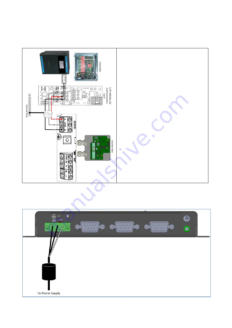
In the controller, connect the Comm-Box to the controller's communication card. Refer to the
following illustrations.
1. The cable between the external connection
box and the controllers should be a 3 wire
twisted shielded cable (22 or 24 AWG).
2. Connect the wiring as follows:
o
COM to COM
o
The Comm-Box A port is connected to
Controller's A port.
o
The Comm-Box B port is connected to
Controller's B port.
3. The final controller in any chain or branch
requires a 120 ohm terminator.
4. Connect the cable shield wire to the controller
ground strip.
Figure 1: RS-485 Wiring
•
The Comm-Box comes with the power supply wired to the unit. See Figure 2.
Figure 2: Comm-Box power supply wiring


