1
© Munters Corporation, July 2017
QM1154r5
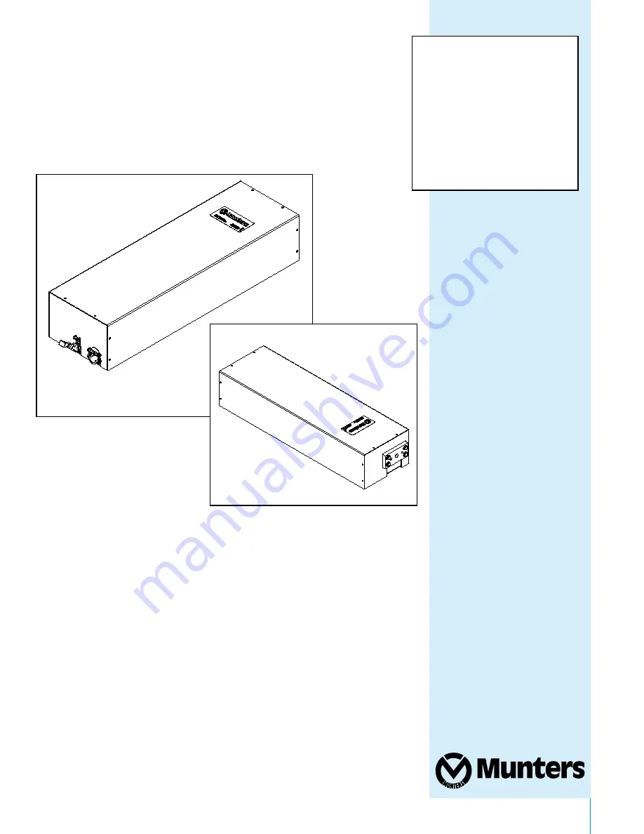
Instruction Manual
BA1701 Series Baffl e Actuator
Models:
BA1701 • BA1701-30
Aerotech
Baffl e Actuator
Страница 1: ...1 Munters Corporation July 2017 QM1154r5 Instruction Manual BA1701 Series Baffle Actuator Models BA1701 BA1701 30 Aerotech Baffle Actuator ...
Страница 2: ...read all instructions carefully before beginning installation Warranty For Warranty claims information see the Warranty Claims and Return Policy form QM1021 available from the Munters Corporation office at 1 800 227 2376 or by e mail at aghort info munters com Conditions and Limitations Products and Systems involved in a warranty claim under the Warranty Claims and Return Policy shall have been pr...
Страница 3: ...ers Page 1 Unpacking the Equipment 4 1 1 Parts List 4 1 2 Dimensions 4 2 Installation Instructions 5 8 3 External Cabling Methods 9 10 4 Electrical Wiring 11 5 Operation 12 13 6 Maintenance 14 7 Troubleshooting 15 17 8 Exploded View and Parts List 18 19 ...
Страница 4: ...le Actuator ID Qty Cat No Description A 4 KS2463 1 4 x 1 5 Hex Lag Screw ZP B 2 AC1039 3 16 Cable Clamp ZP C 4 KN1001 1 4 20 Hex Nut ZP D 1 AC1037 Cable Assembly 60 L 1 4 20 THRD ENDS E 1 AC1048 Thimble for 1 8 Dia Cable ZP F 4 AC1286 3 5 Dia Pulley w Hanging Bracket CI G 4 KS2650 5 16 x 5 Open Eye Lag Screw ZP H 2 AC1038 5 16 x 9 Hook Eye Turnbuckle AL ZP Actuator Specifications Power 110 120 VAC...
Страница 5: ...vicing Step 1 Install the actuator in the location shown on your ventilation system drawing or as shown in Figures 1A and 1B Secure to framing using 4 Lag Screws A See Figure 2A for typical installation of a ceiling mounted actuator See Figure 2B for typical installation of a wall mounted actuator Figure 1A Figure 1B ...
Страница 6: ...5 Installation Instructions Chapter 2 CEILING MOUNT Figure 2A SIDE VIEW 0 0 231 4 LOOKING UP FROM FLOOR WALL MOUNT Figure 2B SIDE VIEW FRONT VIEW 1 2 2 3 4 5 6 5 3 7 8 9 A B C B D E F G H G I J 7 8 9 A B C B D E F G H G I J 1 2 2 3 4 5 6 5 3 ...
Страница 7: ...through and attach to the Ball Nut Flange using 4 Nuts C See Figures 3 Figure 4 Figure 3 K L M N O P O Q R S T U V V T W R S X N Y P K X S Z S Z U M L Q M Z _ Z L V a b c d T e X T f Q b g _ T h N i P j Q S S k Z d l S Q M T l L S S T X N m P j Q S S g M L n Step 3 Secure Open Eye Lag Screw G to wall in direct line with BA1701 Then attach Pulley F to Eye Screw as shown See Figures 4 Q S S K L M m ...
Страница 8: ...s through eye of turnbuckle and secure with Cable Clamp B See Figures 5 Installation Instructions Chapter 2 Figure 5 Figure 6 s v w v x z v v o v w w r w t q w x z Step 5 Place Cable Thimble E over hook end of Turnbuckles H Place Cable Assembly D in groove of Thimble E See Figures 6 w s v w v v p p v v w x z o p q r s p t u v w x y z s v w v x z v v o v w w r w t q w x z w s v w v v p p v v w x z ...
Страница 9: ...t the same rate and the normal load will be applied to the curtain machine Note When a Hand Winch is connected to the inlets and two free pulleys are connected in line the inlets will travel at the same rate as the baffle machine For every 1 the baffle machine travels the inlets will move 1 The normal load will be applied to the baffle machine ª BAFFLE MACHINE AND CABLING WITH HAND WINCH INSTALLED...
Страница 10: ... baffle machine travels the inlets will move 2 Twice as much load will be applied to the baffle machine therefore it will have half the pulling capacity Note When a Hand Winch is connected to the baffle machine and a Free Pulleys is connected to the inlets the inlets will travel at half the rate of the baffle machine This is because for every 1 the baffle machine travels the inlets will move Only ...
Страница 11: ...ker Catalog No SY2010 Step 3 Open Close and Neutral outputs from the air monitor control are to be wired to Open Close and Neutral inputs in actuator See Figure 7 Step 4 Turn on the electrical supply to the Actuator and the Air Monitor Control It is now ready to operate WARNING High Voltage disconnect power before servicing Figure 7 Ø Ù Ø Ú Û Ü Ý Ø Ú Ü Þ Ù Ú ß à á â ã ä å æ ç è é ê æ ë ì á í î ï ð...
Страница 12: ...mit Switch against Guide Block so that it activates Close Limit Switch and tighten screws See Figure 9 Manually run Baffle Machine open about 1 and back close to check for proper full close position Figure 9 Operation 5 ü ý þ ÿ Figure 8 Note The baffle machine is shipped with the Open and Close Limit Switches set for mid range operation See Figure 8 These switches MUST be set for your installation...
Страница 13: ...achine to full open position for baffles or inlets Slide Open Limit Switch against Guide Block so that it activates Open Limit Switch and tighten screws See Figure 11 Manually run Baffle Machine close about 1 and back open to check for proper full open position Step 3 Place all switches and controls in AUTO Test operation of Baffle Machine using Air Monitor Control or Environmental computer contro...
Страница 14: ...within the inlets operating range This should be per formed every 6 months 5 CHECK ELECTRICAL CONNECTIONS With the power turned off to the unit verify that the termination points are secure and all wires are in good condition This should be done yearly 6 CHECK GEARMOTOR No lubrication or adjustment is needed on the gearmotor Some maintenance may be necessary for reliable operation if the unit will...
Страница 15: ...e is present replace DPDT relay 4 Check output of Actuator control to make sure the actuator is receiving a signal to close If voltage is not present check main electrical service panel in building and wiring from control B OPEN 1 Check for 120VAC at blue and red wires on motor If voltage is present repair or replace motor 2 Check for 120VAC at 9 and 1 neutral If voltage is present replace limit s...
Страница 16: ... G D 9 a K G D 9 a K b a c 1 J 3 4 G 7 8 G 7 8 d C SIGNAL 120 VAC CONTROL e f g h i j k l m f h e k e j h g m n o p o f i j f q j e RELAY r m f s e r o n p t s u v g j w x y Q N _ z Z Z Z Z b K 9 1 J 7 1 J D 8 9 K K J 8 1 K F L 9 1 9 D J 7 2 7 0 0 0 9 a J D 7 K 8 c J 8 1 c 7 1 1 c J L 1 a 1 8 c 1 9 a 7 D a c 8 c 1 c J 8 7 G J L 9 I K 1 K F 7 K F J L 9 6 K F a 1 9 0 L 9 1 9 D T 1 9 J K 9 1 2 K 1 J ...
Страница 17: ...EN LIMIT CLOSE LIMIT SWITCH º º º º À ª À ª Á º À Â Ã Ä Å Æ Ç È É Ê Ë Ì Å Ç Ä Ê Ä É Ç Æ Ì Í Î Ï Î Å È É Å Ð É Ä RELAY Ñ Ì Å Ò Ä Ñ Î Í Ï Ó Ò Ô Õ Æ É Ö Ø Ù º º º º Ú º º º º Á Û Ü Ý Þ ß ª à á ª ª ª â ã À ª Â Â Â â À Â À À Â Â Â ª ª á ª â ª À â á â ª ª Â ª ã ª â ª Â ª SIGNAL 120 VAC CONTROL Figure 13 BA1701 30 ...
Страница 18: ... Munters Corporation July 2017 18 QM1154r5 Exploded View 8 ...
Страница 19: ...AC1019 Snap Acting Switch with EXT Spring 15A 2 17 AC3120 DPDT Relay 20A 2HP Max 120VAC Coil 1 18 AC1427 Capacitor 6MFD 250VAC Sealed 4 Leads 1 19 FC1095 8 Pole Terminal Block 12 AWG Max 20A 1 20 KE1151 Connector C500 3 8 Romex Clamp ZP 1 21 KX1101 Snap Bushing 7 8 D WHT or BLK PL 1 38 KW3002 Flat Washer 1 4 Type A Narrow SS 5 39 KS1020 Cap Screw 1 4 20 x 1 75 Hex ZP 1 40 KN1558 Nut Keps 1 4 20 ZP...
Страница 20: ...739 235 Italy Munters Italy S p A Chiusavecchia Phone 39 0183 52 11 Japan Munters K K Phone 81 3 5970 0021 Korea Munters Korea Co Ltd Phone 82 2 761 8701 Mexico Munters Mexico Phone 52 818 262 54 00 Russia Munters AB Phone 7 812 448 5740 Singapore Munters Pte Ltd Phone 65 744 6828 South Africa and Sub Sahara Countries Munters Pty Ltd Phone 27 11 997 2000 Spain Munters Spain S A Phone 34 91 640 09 ...