


1
Table of contents
Preface
................................................................................................................................2
Warnings and notices
.......................................................................................................2
FCC Regulations
....................................................................................................... 3
FCC RF Exposure Information (SAR)
..................................................................... 3
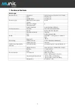
1. Hardware features
........................................................................................................5
2. Hardware description
..................................................................................................6
2.1 External view
............................................................................................................6
2.2 Internal view
.............................................................................................................6
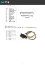
2.3 OBD connector pin out
.........................................................................................7
2.4 OBD adapter wires
.................................................................................................7
3. Preparing/installing the device
..................................................................................8
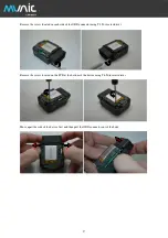
3.1 Open the device
....................................................................................................8
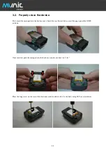
3.2 Properly close the device
................................................................................... 11
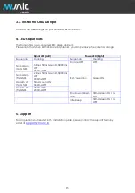
3.3 Install the OBD Dongle
......................................................................................... 13
4. LED sequences
............................................................................................................. 13
5. Support
.......................................................................................................................... 13
Содержание C4D-4G4USAA V8+
Страница 1: ...C4D 4G4USAA_V8 INSTALLATION GUIDE V 1 6 21 12 2021...
Страница 11: ...10 Device is now open...