MultiConnect
®
microCell Cellular Modem
MultiTech Systems
MultiConnect
®
microCell Cellular Modem
MultiTech Systems
MultiConnect
®
microCell Cellular Modem
MultiTech Systems
Quick Start
Quick Start
Quick Start
Overview
The MultiConnect microCell (MTCM) is a compact communications
device that provides cellular capabilities for fixed and mobile applications.
Package Contents
Your package includes the following (varies with model):
Device
1- MultiConnect microCell cellular modem
Antennas
2 - External antennas
Documents
1 - Quick Start, 1 - Warranty information
Other Items
1 - Mounting rod, 4 - Clear adhesive bumpons
Additional Information
For more information, refer to the user guide for your model at:
https://www.multitech.com/brands/multiconnect-microcell.
Note:
If this quick start has been updated, it will be at that location..
Dimensions
The device dimensions are: 2.105 in x 0.780 in x 1.79 in (5.35 cm x 1.98
cm x 4.55 cm)
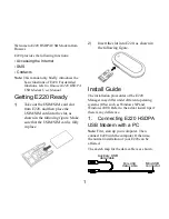
Side Panels
Connectors
The device has the following connectors:
■
USB
1 USB connector,
■
SMA
2 female SMA connectors, labeled CELL and AUX
■
SIM
1 micro-SIM slot, between the SMA connectors
LED Descriptions
The device contains the following LEDs:
■
POWER
- Lights when the device has power.
■
LINK
- Blinks when the unit is functioning normally.
■
SIGNAL
- Three programmable signal LEDs. Require users to
write code to control. Non-functioning by default.
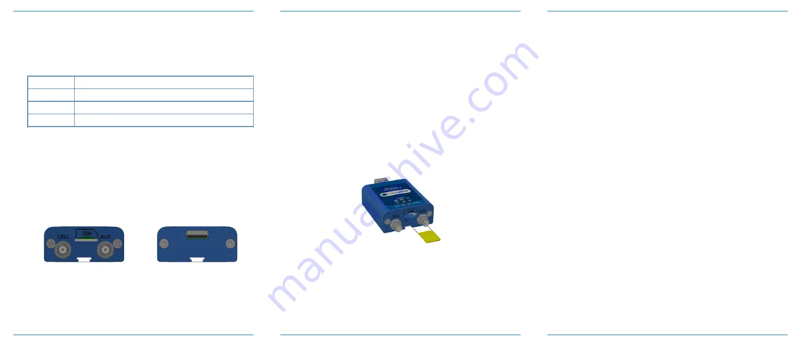
Installing a SIM Card
To operate the device on a cellular network, you need a micro SIM card
(3FF) from your carrier.
To install the SIM card:
1.
Locate the SIM card slot on the side of the cellular modem.
The slot is labeled SIM.
2.
Push the SIM card into the slot with the contact side facing
up as shown. The SIM card locks into place.
Installing the Cellular Modem
1.
Connect antennas to the antenna connectors.
2.
Connect the USB connector to your computer, either
directly or through a hub.
The USB connection powers the device and the
POWER
LED lights.
Dual Carrier
This device uses a cellular radio with dual firmware meaning that it can be
used on two different carrier networks (not simultaneously). The device
can be used on either the Verizon or AT&T/other networks.
To check that your device is configured for the desired network:
AT#FWSWITCH?
If response is: #FWSWITCH: 0 The device is configured for AT&T/other
networks.
If response is: #FWSWITCH: 1 The device is configured for Verizon.
To switch carrier networks:
From AT&T to Verizon:
AT#FWSWITCH=1,1
From Verizon to AT&T:
AT#FWSWITCH=0,1
Note:
For the Link status (LS) LED to function, you must issue the
command AT#GPIO=1,0,2 any time you use the firmware switch
command (AT#FWSWITCH=0 or AT#FWSWITCH=1).
Mounting Device
1.
Locate the groove on the bottom of the cellular modem.
2.
Slide the mounting rod through the groove.
3.
To secure the rod to the desired surface, place and tighten
two screws in the holes on either end of the mounting rod.
Refer to the user guide for an illustration and the
dimensions for screw placement.